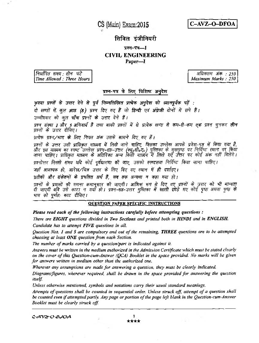
UPSC IAS 2015 Question Paper for Civil Engineering Paper-I
Finished viewing? Save it for later —
Download UPSC IAS 2015 Question Paper for Civil Engineering Paper-I (PDF · 15 pages)About UPSC IAS 2015 Question Paper for Civil Engineering Paper-I
UPSC IAS 2015 Question Paper for Civil Engineering Paper-I is available here for free download. Published by UPSC for UPSC CSE (IAS), this question paper can be viewed online or downloaded as a PDF (15 pages). Candidates preparing for UPSC CSE (IAS) can use UPSC IAS 2015 Question Paper for Civil Engineering Paper-I to understand the exam pattern, the type of questions asked, and the overall difficulty level.
Frequently Asked Questions
How can I download UPSC IAS 2015 Question Paper for Civil Engineering Paper-I?
Open this page and click the Download button to save UPSC IAS 2015 Question Paper for Civil Engineering Paper-I as a PDF. It is completely free on AglaSem Docs.
Is UPSC IAS 2015 Question Paper for Civil Engineering Paper-I free to download?
Yes. UPSC IAS 2015 Question Paper for Civil Engineering Paper-I can be viewed online and downloaded as a PDF free of cost on AglaSem Docs.
How many pages does UPSC IAS 2015 Question Paper for Civil Engineering Paper-I have?
UPSC IAS 2015 Question Paper for Civil Engineering Paper-I contains 15 pages, which you can read online or download together as a single PDF.
Where can I find more UPSC CSE (IAS) study material?
You can find more UPSC CSE (IAS) question papers, sample papers, syllabus, and answer keys on AglaSem Docs.
UPSC IAS 2015 Question Paper for Civil Engineering Paper-I – Text
Read the full text of this question paper below — useful to quickly search, copy and reference the content online without downloading the PDF.
📄 View text version (15 pages)
Page 1
f%facT i i f P p r O
W - 'R - 1
CIVIL ENGINEERING
Paper—I
ftv ffc r t m : rffcr w t 3ff> : 250
Time Allowed : Three Hours Maximum Marks : 250
5TFT-W % feTTT j%f3re arg^T
fWT m f % 'jm ft ftwfrlfcM V&F 3F^W &TFt%$W :
$ W&f % 3>?r &T5 (8) WFT far ny $ i t f ^ t W? m fcft f r f f $ tl
o w^r w i f $ t o t ft
w? tmr l Jh s zfPrwf $ mr m¥f jtft¥ #' # ?f#^ # wr-d-w x^r wft #t
£ ^f7T
v m / w t $ fen* firm sfa ?77^ far ^ #'/
m )1 £ jw 77/i^cf mm #* fM wrf^i f^rw ^rdw smi? yfcw-m % fan mr t,
sifc f?r mm w w wft- w -ztk (Ffofftofy) ^ w qr t o
^R7 sflfan mm $ 3?fofcki sht m f mm h frnk w ^ wr sr^
wOm $[??& wm vfe ffwvm ¥f w*, fm f^r wftt
o^f m m 3 , zntw /f& r u m $ far ^ ^ pt #' eft ?w/V^/
3cfW #r w'^7 £ Trfrm srf i, m uw 3pw ^ wr m wti
mwf $ srmf ¥f whj mr^im ¥f wpfti w f ^ wr # fa? w w tf £ zm # *# mmr
$- zjnpft vft m^r > mr wti yiFT-w-^riT 5#ctw #* ^7<# m i w ^ ?& $
WT # y 7/^: W? # f c f /
OUESTION PAPER SPECIFIC INSTRUCTIONS
Please read each of the following instructions carefully before attempting questions :
There are EIGHT questions divided in Two Sections and printed both in HINDI and in ENGLISH.
Candidate has to attempt FIVE questions in all
Question Nos. 1 and 5 are compulsory and out o f the remaining, THREE questions are to be attempted
choosing at least ONE question from each Section.
The number o f marks carried by a question/part is indicated against it.
Answers must be written in the medium authorized in the Admission Certificate which must be stated clearly
on the cover o f this Question-cum-Answer (QCA) Booklet in the space provided.No marks willbe given
for answers written in medium other than the authorized one.
Wherever any assumptions are made fo r answering a question, they must be clearly indicated.
Diagrams/figures, wherever required, shall be drawn in the space provided fo r answering the question
itself
Unless otherwise mentioned, symbols and notations carry their usual standard meanings.
Attempts o f questions shall be counted in sequential order. Unless struck o ff attempt o f a question shall
be counted even if attempted partly. Any page or portion o f the page left blank in the Question-cum-Answer
Booklet must be clearly struck o ff
C-cA~V2-0-£>^0cA 1
★★★★
Page 2
VI " V-
---
--
SECTION—A
Q. 1(a) 6m AB f^*T AD SRI % ft^T WT I, %T ^ w
11 m 10 kN11 W f% *pft f ^ f t #, WcPT AD 3 ^T
f^rsrf^T
A rod AB 6 m long is held against sliding by a string AD. The rod weighs 10 kN.
Determine the tension in the string AD assuming that all surfaces are smooth. 10
4m
k 1
Q. 1(b)? M t ^ ftf^ f ¥ ^ r f Tctt 11 to r
WIT f^TT tfWT t f% ^ «RTTCT
^ i <fr gsrnj i /;
The global stiffness matrix of a structure contains rigid body displacements. Describe how
to modify it to account for nodes having zero displacements. Give two approaches. 10
Q. 1(c)
A B c D
A* TT ~UT IX El = Constant
I = 200 x 10"6 m4
5m , 4m 6m E = 200 GPa
*■--------------*------------- ¥----------------k
f^T if f^r TT^r ^ M, STT^f ( ^ T ) 3 n ^ *FTJ%, ^ ^nrtf ‘B’ 10 mm %fccT
FfaT 11 smjijf f^cR^T ^ I
Draw the B.M. diagram for the beam shown in figure when support B settles by 10 mm,
using moment distribution method. 10
Q. 1(d) ^Tcfr tpr W W T ^
^ TftUm ft -Ft T5T 11 3m
t (?Nf fom t ) 0.01 cm/s t afk
1m^ ttcT t 3TTO 0.1 cm/s (fNT ftw $) 11
W ^ ^TcT ^ ^frTW 3fk ^srfsfT ^ e H t % 3TFS MWoptfcTcfl
C-<XV& 0-& J& J\ 2
i I A i
XTXX
Page 3
thick sand with coefficient of permeability 0.01 cm/s (in both directions) overlain by
1 m thick fine gravel with coefficient of permeability 0.1 cm/s (in both directions).
Determine the coefficient of permeabilities applicable for horizontal and vertical ground
water movements through the layer. 10
Q. 1(e) ^PT v, WT ^ r^ ^f ^
#cfT t I 1.5 m %ry 0.8 m s'1 W WT t i f M k *TFT
% 0 .5 m 3 k 1.25 m MT? % f ^ T I
At the entry of the pump intake the velocity v varies inversely as the square of the radial
distance r from inlet to suction pipe. The velocity is found to be 0.8 ms-1 at a radial
distance of 1.5 m. Compute the acceleration of flow at radial distances of 0.5 m and at
1.25 m, from the inlet assuming the stream-lines to be radial. 10
Q. 2(a) f ^ T ^Kt (Borrow pits/sites) % ^ ft£\ ^4d®£T I
3 s r f t e 1.0 x 10⁵
J**v. m3 *TT sfk » 0.75 W I (In-situ)
(^nrnfr enw) # f¥ $ f^ r fan w 11
Borrow site Void ratio Total cost per cubic meter
1 ,0.8 Rs. 200
2 1.15 Rs. 180
3 1.25 Rs. 175
wf % w r to ra fr ^ i
Material for an earthfill was available from three different borrow pits/sites. In the compacted
state the fill measured 1.0 x 10⁵ m3 at a void ratio of 0.75. The corresponding in-situ void
ratio and cost (cost of material and transportation) of the material for three sites are as
follows :
Borrow site Void ratio Total cost per cubic meter
1 0.8 Rs. 200
2 1.15 Rs. 180
3 1.25 Rs. 175
Determine the most economical site for the above earthfill work. 15
C~cA~V2r<y£>sSOcA 3
★★★★
Page 4
^cT, 2.5 m ^ 11 I-%^FT % ^JWt 3^t f ¥ ^ q#%T 200 x 200 mm
^ ^ 800 mm x 6 mm 11
^cTRJcf tf^rrr ^4-5R)cj( tf^TT ^ Rw 110 MPa, 165 MPa
3?tT 100 MPa sFTCT: ?t <ft, tf^T ^ t o r ^ MR^k ^ I
J!^< ^T W*TTC *1vj|<3i^N fa>i|| yff ^i'+>dl 1? 1
Two wheels, placed at a distance of 2.5 m apart, with a load of 200 kN on each of them,
are moving on a simply supported girder (I-section) of span 6.0 m. The top and bottom
flanges of the I-section are of 200 x 200 mm and the size of web plate is 800 x 6 mm.
If the allowable bending compressive, bending tensile and average shear stresses are
110 MPa, 165 MPa and 100 MPa respectively, check the adequacy of the section against
bending and shear stresses, self weight of the girder may be neglected. 20
Q. 2(c) 4i^ tr ^ w 3pjr n ^rfcP^T (# cr tttsct) (fcR^) afhr f ^ F (f»r)
ePTT^ 3fRkul % % ^TFT 100 ms-1 91ipHd
M It
TOW t 5 ~m # r -90°C dIHHM 'CK ^ W*T 1% Z-TcT
^TR (T T frm % fcR p = 7.7 kg m“3, M T 1.2 x 10~5 Ns) cFTWT
V fm 295 ms"1 11
TjTif Tjcin?^ aflr Tn^er # r snf^wr ^ sp|w ^rf^RT
# ferq 1% #r sryrN -# ^ ; i
^*T MHPT W 1.2 kg m”3 3^T WPRTT 1.8 x 10⁻⁵ Ns t I
In order to predict lift and drag forces on a scale model of an aircraft during a section
of operational envelope, involves sea level flight at 100 ms”1, where the speed of sound
may be taken as 340 ms-1.
It is proposed to utilise cryogenic wind tunnel with Nitrogen at 5 atmosphere of pressure
and a temperature of-90°C (p = 7.7 kg n r 3, viscosity 1.2 x 10~5 Ns for nitrogen). The
speed of sound in nitrogen at this temperature is 295 ms-1. Determine the wind tunnel
flow velocity, the scale of model to ensure full dynamic similarity and, the ratio of forces
acting on the model and prototype.
Mass density of air 1.2 kg m“3 and viscosity 1.8 x 10⁻⁵ Ns. 15
C-<A‘V&0-£>JV*A ' 4
★★★★
Page 5
Q’ 20 kN 20 kN
c D
-------3v
2m 1m 1m 2m
¥-------- — ¥■-------------------------- ¥-¥------- ---------r
far g*T $ feft ‘A’ *R ^cTFT 3^T ‘B’ ^ ? VW TOFT. TT 3;srf£R f a M
irf^TT sgftTf sHTT ^ I El = WF$t?Z 3 I
Determine the slope at A, vertical deflections at B and mid span using the moment-area
theorem. Take El - Const. 15
q . 3(b) ^ ir f t ^ ,^ t t e r , apr^FS' tftrcr ^r 60 kN ^ tf%rr
7.5 kNm/m ^rpfr % ^ *R T 3R TST t , % ^ T T 11
M 30 ite ^ sfft Fe 415 frs W \
= 30 mm
^ FT = 1.5 MPa
^T = 2 MPa
^ o cr ^f^nfr - 9
Design a section of wall of a water tank on uncracked basis to resist a pull of 60 kN and
a bending moment of 7.5 kNm/m width producing tension on the water face. Use M 30
concrete and Fe 415 grade steel.
Effective cover = 30 mm
Permissible stress in direct tension in concrete = 1.5 MPa
Permissible stress in bending tension in concrete = 2 MPa
Modular ratio = 9 15
Q. 3(c) cffa WT f e r ^ fapfNR W f I W % Tftfr t :
Pipe D (mm) L (m) f
A 150 600 0.020
B 100 480 0.032
C 200 1200 0.024
MI^H wr ^ i ^
C -cA -V Z -0~& JV cA
Page 6
Pipe D (mm) L (m) f
A 150 600 0.020
B 100 480 0.032
C 200 1200 0.024
Determine the flow rate in each pipe. Minor losses may be neglected. 20
q . 4(a) to t o wt ^
i
What is the preconsolidation pressure ? Describe a method to determine the preconsolidation
pressure. 15
Q. 4(b) ^ ^T' $ ?RT ^ W I ^ T ^ 3TWFT
155 N-m (Torque) s rr^ rw r 11 ^F*T 100 mm 3^r ci^i{
150 mm 11 ftnrr (Cu) w ^ % ot Rrt, ftwn; # c
3 p f |^ *^=*T 3TTO ^TPJcT ^ M ^ I
An in-situ vane shear test was conducted at the bottom of a borehole in a soft clayey soil.
A torque of 155 N-m was required to shear the soil. The vane was 100 mm diameter and
150 mm long. What was the undrained shear strength, Cu of the soil ? Derive the relevant
expression relating to torque vane dimension, and undrained shear strength of the soil.
15
Q. 4(c) ftdPOf W ^ WT ^ tWTcf sHTT ^[faf W t l ^
ftft f^T^T ^Ffc^ 19 kN/m3 ^ xrfjteT 3TTO ftqfa 30° t , ^STR?T TBT f I <4^
' f^W T ^ cT ^ f^TT^T git i M 30
<r Fe 500 ^ w 11
C-cA‘V Z -<y '2>JO <A 6
A I A i •
AAAA
Page 7
dry earth having a density of 19 kN/m3 and angle of repose of 30°. Design a counterfort
in flexure only using the limit state design. Take M 30 grade of concrete and Fe 500 grade
steel. 20
3m
0.5 m
6m
0.5 m
3m
■+— J[ p l a n
5m 0.5 m
(a)
(b) SEC A-A
SECTION—B
Q. 5(a) (i) w r, ^ ^ m fowifacft
1.95 x 10⁻³ m V 1 ? 1500 ft, ¥T ^TRT ^ I WT ef^T4 if
wdr& i w m WT W 11
Determine the diameter of the vertical pipe needed for a flow of a liquid of kinematic
viscosity 1.95 x 10"3 m2s“1 at a Reynolds number of 1500. The constant pressure is
maintained throughout its length. 5
C -cA 'V ^ -O & 'JV cA 1
Page 8
#TeT # cTwf = 1 8 km, Pl*-*Kui = 250 m3s-1
W U i = 2.5 m, ^Tef i t = 50 m
^Tcf W WcT ^erfsR #cT 1 : 50 «T #eT 1 : 500 *TC ^TRT W t I
;■ m fa 12 ^ 11
KTteT ^ 3?tw (m/sec) 3ffc 3T^r WT ^ I
Prototype data of Tidal Channel are as follows :
Length of channel = 18 km, Discharge = 250 m3s_1
Depth = 2.5 m, Width of the channel = 50 m
Model is built with a vertical scale of 1 : 50 and a horizontal scale of 1 : 500
Tidal period is 12 hours
Compute the average velocity in ms-1 and tidal period in the model. 5
Q. 5(b) ^ sjs*T cTT^T 3 '("ftlcfttH a = 3Vv W TFT 11 t - 2 sec Tt,
8m c[i] 6 m/sec 1 1 WT t = 4 sec TTC W^T f ^ W , c37?T f*PFT$f I
a = x^T W v = %^r |
A particle moves on a vertical line with an acceleration a = 3-s/v . At t — 2 sec, its
displacement is 8 m and velocity is 6 m/s. Determine its displacement, velocity and
acceleration at time t = 4 sec. a = acceleration and v = velocity. 10
Q. 5(c) TTcff tw z ^Tt 12 m en^T t , 11 ^ t WT
t , <rt 3T$fcr y rr (couples) 50 kNm ? 75 kNm 5 m W9 m
f tr t % '% r ^TT TFT | |
w rc M w ^ # w t cmM ^tft iH
3TT% I
A horizontal shaft 12 m in length is fixed at its ends. When viewed from its left end, axial
couples of 50 kNm clockwise and 75 kNm counterclockwise act at 5 m and 9 m from the
left end respectively.
Determine the end fixing couples and the position where the shaft suffers no angular
twist. 10
Q. 5(d) ^ ^T frfc' WTcTT ^t°T 15° t (*#T % "TNT W t )
3 'HK 18 kN/m3 ^ sr*T74t #teT 3TR5 <() = 35° 11 'm
M f ftefcTT it ffc tf To ^ : (i) WRTT ^ ¥<T % #TW Tfef
- *fT f^TR^RT Ft, (ii) uR $ W *fT # T ^FTRR Ft TFT Ft I
c-< av& -o-& 'jo< A 8
★★★★
Page 9
has a saturated unit weight of 18 kN/m3 and an effective angle of internal friction, § ~ 35°,
Determine the factor of safety against failure of the slope (i) when the slope is completely
dry or submerged but without seepage, (ii) when seepage occurs at and parallel to the
surface of the slope. 10
5(e) Fe 410 ^ it 300 x 10 mm sfk 280 x 10 mm t tts
vrirrv ? $ w I % ^ t a i w ti
ite z veiled ^ ^ t in i e r
^ i
^ 3TTO = 250 MPa
ym„
1mo = 1.1
'S«rc, < 3rnr? S'+cf) = 1.5
Design a welded lap joint to join two plates of size 300 x 10 mm and 280 x 10 mm in
Fe 410 grade steel to mobilise the tensile strength of the plates using field weld.
Yield strength of material = 250 MPa
v/'m
ti--o = 1.1
Partial safety factor for field weld - 1.5 10
p *~i _ I W
C-vrv2rO -& JVcA 9
Page 10
TOT ^ ^rfaT w l l 3^rf£R 3(WFT ®RT 10 kN ^ f^TSjfftc
W ^TT cPTM W t l ^ ^ 3R W I ¥f<facT (f%*TC ^ f ) f^T^T TO ^ i
A beam has a cross-section shown in figure. It is subjected to a vertical shear force of
10 kN at a given section. Determine the shear stress distribution on the section. 15
Q 6(b) (i) vRwnrf ^ ftsjcr wTefT^r 3 ^ rt tr wm w 11 w ^ srcr
20 m t , eft WTWf^T ^ m3s_1 V<W I
WTcTT^T c P ^ = 1500 m
= o.02
W TO Wi ^ r n = 300 mm
‘A’ TR WSEL = 200 m
‘B’ ^T WSEL = 185 m
A booster pump is installed in the pipeline between two reservoirs. If the energy
added by the pump is 20 m, determine the flow rate in the pipeline in m3s_1.
Length of the pipeline = 1500 m
Coefficient of friction = 0.02
Diameter of the pipeline = 300 mm
. : WSEL of A - 200 m WSEL of B = 185 m 5
10
★★★★
Page 11
f^^Tuf = 5000 m3s_I, 3cTFT - 1 : 2500
vm it = 4.50 m
^nPrrr ^ 11
Compute the shear stress acting on the river bed for the data given :
Discharge = 5000 m3s“1, River bed slope = 1 : 2500
Depth of flow = 4.50 m
Assume the river to be wide. 4
Q, 6(b) (iii) ^ $ 3^rf FlPr 9.0 m ? M&S WTT 0.12 11
TO - ^ T Y l t t e TT^jf 3fk PrWT^T cftsRTTI
A hydraulic jump has an energy loss of 9.0 m and the downstream Froude number
is 0.12.
Determine the initial depth and the discharge intensity. 6
Q. 6(c) (i) % fM P rw i
(ii) fe ^ ^IHlf^d I
(iii) TOTT ^TRTTT qR ^II I
(iv) ^ irfMcRT ^qqlRldl3Tt' fM I
(i) State the Abram’s law on water-cement ratio. 5
(ii) Name the various grades of ordinary Portland cement. 5
(iii) Define characteristic strength of reinforcing steel. 5
(iv) State any five applications of prestressed concrete. 5
Q. 7(a) (i) f^T tT3 ^ ^ Cv = 0.98 ? Cc - 0.62 i t eft, 3ifaPpr
& *\{ 5fTcf I ^rT : Vj = 2.006 m s -1, g = 9.81 ms-2 ft
m ^ Prsrf^r ^ tf^ r i
For the sluice gate shown in Figure, if Cv = 0.98 and Cc = 0.62, what is the height
of the opening ? Given V{ = 2.006 m s-1, g = 9.81 ms~2. Also determine the flow per
unit width. * 5
C rJC V & 0 -4 > JO JK 11
Page 12
1(V) : 2(H) t , 3f Wt # WTTf 1.5 m i l tfeft ^ 1 x 10⁻⁴ f>1
¥^RTT ( w f a ) = 0.2 11 3PJ3WT (ST^T^fa) ^ t c T ^ ^
^ 3m TFT t I $ N > m W1 cjjffc^ui ^ |
The uniform flow depth is 1.5 m in a trapezoidal channel of bottom width of 20 m
with a side slope of 1(V) : 2(H). The bed slope is 1 x 10⁻⁴. Manning roughness
coefficient is 0.2. The downstream control raises the water surface by 3 m. Classify
the profile. 5
Q. 7(a) (iii) sfiW ^R ^TcT % M ^JZl f e l W I ;
% T i = 9 m , n = 0.017, S0 = 1 : 4000
D/S 7fi?rr( = 6.80 m, U/S WTlf = 3.6865 m, = 48.748 m3s_1
firm ftftr ^ h r ^r% ^ cF^rf P i^ iM i
Following data are given for a rectangular channel :
Width = 9 m , n = 0.017, S0 - 1 : 4000
D/S depth is 6.80 m, U/S depth is 3.6865 m
Discharge 48.748 m3s_1.
Using single step method compute the length of profile. 5
Q. 7(b) 9 ^f°T w s r ^ y r 3 ijwti rftrc f^m w t \ w *ft
0.4 m 11 cfT3[\i (w rjf) 12 m I ^ «Pbr t^ T 3 %Zl j t f
1.2 m 11 ^TTRPT (^t^upr) c - 50 kN/m2, ^TTT y = 18 kN/m3.
'• (i) =30 ^ «eTFF ^ # ) (ii)
^ 3m-3WT f^ R H tr 3rrmfer, (iii) w ^ I W t (*ttP r m yw
3f^PT $^dT a = 0.8)
f« - ' '( . ,
A pile, group consists of nine friction piles driven into a deep layer of clay soil. The
diameter of each pile is 0.4 m, the embedded length is 12 m and center to center spacing
of the piles is 1.2 m. The soil has cohesion, c - 50 kN/m2, unit weight, y — 18 kN/m3.
Determine (i) the block capacity of the pile group using a factor of safety = 3.0, (ii) group
capacity based on individual pile failure criterion and (iii) design capacity of the pile
groups (Assume adhesion factor a = 0.8) 20
C-<A‘V&-0-£>'JOcA 12
★★★★
Page 13
w fr f^rrT r, = 0.5 m •• >• . .
s r ^ f t ^R4)fl ft^rr r2 - 0.3 m
IcnRr^t v r ffc ^ (Pf) *ptt = 80°
w % ^ W? w f # = 0.25 m
^ ft 3TTC5 4 m3s_1 ^ WT t ^ W R 300 rpm 11
^ «cfc #*T p2 f^ra% Wft tf^Tcft W T f%W I
ZW^T 3 TTpft SKT ^ 3^T W Tff^T ^TTcJ^T I
TTT sTRI ^RTrr ^ WTeft cJMW^I 3^T qftu||i^^M ^rrf^f TTj^Tf I
^%¥T TT ^ ?R^T t sfft f^ ^ W*T ^ t I
A radial flow turbine has the following dimensions :
Outer periphery radius r{ - 0.5 m
Inner periphery radius r2 = 0.3 m
The angle made by the relative velocity at the inlet is (pj) = 80°.
The width of the flow passage between the two sides of the turbine is 0.25 m.
The flow of 4 m3s_1 goes through the turbine when the speed is 300 rpm.
Find theblade angle P2 such that water exit radially.
Find the torqueexerted by the water in the turbine and the power thus developed.
Find the head utilised by the runner and the power resulting therefrom.
Assume no shock at the entrance and blades are of negligible thickness. 15
Q. 8(a) f^ r 3 f^T ^ 3T<hi ^ z \z tr WTcT m ? wr $ ^ %
3TTO S fR fl^ r I TfT : H = 5 m, <|> = 30V C = 0,
p = 90°, hw “ 2.0 m, ysat = 18 kN/m3, ybulk = 17 kN/m3 (above water table),
q = 250 kN/m2.
C-<KV^O-&JO<A 13
Page 14
the wall, and the point of application of the thrust above the base of the wall. Given
H = 5 m, <)>= 30°, C = 0, P = 90°,\ - 2.0 m, ysat = 18 kN/m3, ybulk - 17 kN/m3 (above
water table), q = 250 kN/m2. 15
.q - 250 kN/m2
Ybulk = 17 k N / m 3
H = 5m <j>= 30°, C = 0
hw * 2.0 m Ysat “ 18 kN/m3
3
Q. 8(b)
u, u, u„ u« u. u,
-T f-
5m
fasr ^ u3L3, U3L2 L2L3 % M
For the truss shown in fig. draw the influence lines for force in members U3L3, U3L2 and
L,Lr. The load moves on the bottom chord. 15
C-tA'Y^O-£>JO<A
f r•
14
Page 15
ski to W 11 8 mm ttA^F tTT t 3ftr 6 mm web ^fT 11 ^ ^fW efts’ ‘W’
f^ rfM , w Tfe = Fe 410 200 mm ^ f\ TT ^?TT t- w ^ T $ $ I
A bracket connection shown in figure, consists of a joist cutting welded to the flange of
a column by shop fillet welds 8 mm on flanges and 6 mm on the web. Determine the safe
service load ‘W’, the bracket can support at a distance of 200 mm from the face of the
column if the steel grade is Fe 410. 20
250 mm
250 mm
TTFT f e f y W - 1.25
W ^ ^Rrrr = 250 MPa
Partial factor of safety on shop weld = 1.25
Yield strength of steel - 250 MPa
15
★★★★
Document Details
| Board / Org | UPSC |
| Exam | UPSC CSE (IAS) |
| Type | Question Paper |
| Pages | 15 |
| Updated | 30 Apr 2026 |