ISC Class 12 Sample Paper Geometrical and Mechanical Drawing
Finished viewing? Save it for later —
Download ISC Class 12 Sample Paper Geometrical and Mechanical Drawing (PDF · 5 pages)About ISC Class 12 Sample Paper Geometrical and Mechanical Drawing
ISC Class 12 Sample Paper Geometrical and Mechanical Drawing is available here for free download. Published by CISCE for Class 12, this sample paper can be viewed online or downloaded as a PDF (5 pages). Candidates preparing for Class 12 can use ISC Class 12 Sample Paper Geometrical and Mechanical Drawing to understand the exam pattern, the type of questions asked, and the overall difficulty level.
Frequently Asked Questions
How can I download ISC Class 12 Sample Paper Geometrical and Mechanical Drawing?
Open this page and click the Download button to save ISC Class 12 Sample Paper Geometrical and Mechanical Drawing as a PDF. It is completely free on AglaSem Docs.
Is ISC Class 12 Sample Paper Geometrical and Mechanical Drawing free to download?
Yes. ISC Class 12 Sample Paper Geometrical and Mechanical Drawing can be viewed online and downloaded as a PDF free of cost on AglaSem Docs.
How many pages does ISC Class 12 Sample Paper Geometrical and Mechanical Drawing have?
ISC Class 12 Sample Paper Geometrical and Mechanical Drawing contains 5 pages, which you can read online or download together as a single PDF.
Where can I find more Class 12 study material?
You can find more Class 12 question papers, sample papers, syllabus, and answer keys on AglaSem Docs.
ISC Class 12 Sample Paper Geometrical and Mechanical Drawing – Text
Read the full text of this sample paper below — useful to quickly search, copy and reference the content online without downloading the PDF.
📄 View text version (5 pages)
Page 1
Maximum Marks: 80
Time Allowed: Three hours
(Candidates are allowed additional 15 minutes for only reading the paper.
They must NOT start writing during this time).
All dimensions are in millimeters.
Arcs of circles less than 4mm radius may be drawn freehand.
Candidates are required to attempt all questions from Section A and
all questions EITHER from Section B OR Section C.
The intended marks for questions or parts of questions are given in brackets [ ].
SECTION A – 25 MARKS
Question 1 [25]
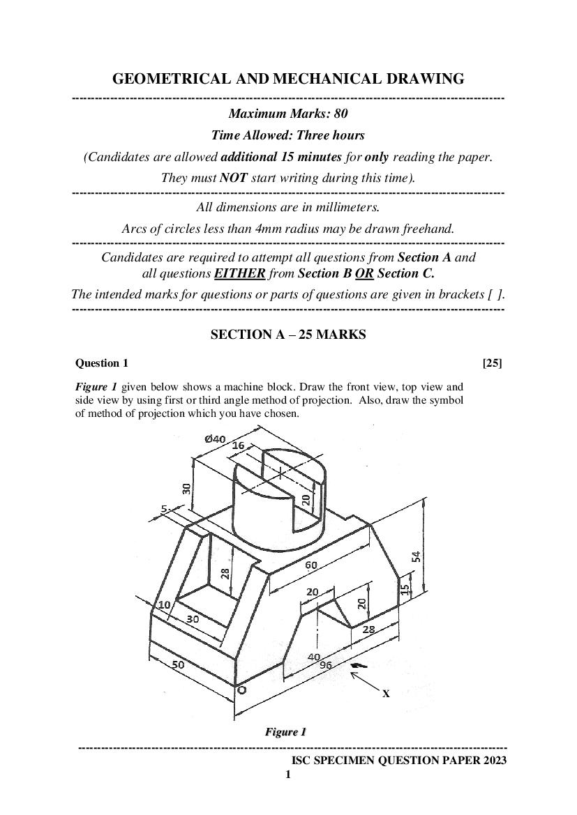
Figure 1 given below shows a machine block. Draw the front view, top view and
side view by using first or third angle method of projection. Also, draw the symbol
of method of projection which you have chosen.
X
Figure 1
---------------------------------------------------------------------------------------------------------------
1
Page 2
Question 2
(i) Figure 2 shows details of components of a flange coupling used to transmit
power from one shaft to another shaft.
Left flange (part 2, Qty 1) is connected to the right flange (part 1, Qty 1) using
hexagonal nut (part 3, Qty 4) and bolt (part 4, Qty 4). Both the shafts (part 5,
Qty 2) are passed through the main central cavity of both the flanges creating
a space for inserting the key (part 6, Qty) in the respective flanges thereby
providing a locking arrangement for the shafts.
(a) Draw full size sectional elevation along A-B of the assembled [25]
components.
(b) Draw the plan (Top View) of the complete assembly omitting all hidden [10]
details.
(c) Draw the left-hand side view of the assembly omitting all hidden [10]
details.
(d) Make a neat parts list for all the components on your drawing sheet. [10]
Figure 2
2
Page 3
(i) Figure 3 given below shows the isometric view of a machine block. Copy the [20]
isometric view.
Figure 3
3
Page 4
angle method of projection Sectional Front View (along A-A), Top View and
Side View.
Figure 4
4
Page 5
method of projection. Copy the given figure. Complete the Front View and
draw its Front View and Top View if its axis is inclined at 450 to Horizontal
Plane and Top View of the axis is inclined at 300 to Vertical Plane.
Given :
Axis height = 75mm
T. V
Figure 5
5
Document Details
| Board / Org | CISCE |
| Exam | Class 12 |
| Type | Sample Paper |
| Pages | 5 |
| Updated | 29 Aug 2026 |