Goa Board Class 12 Question Paper June 2019 Industrial Electronics and Instrumentation
Finished viewing? Save it for later —
Download Goa Board Class 12 Question Paper June 2019 Industrial Electronics and Instrumentation (PDF · 3 pages)About Goa Board Class 12 Question Paper June 2019 Industrial Electronics and Instrumentation
Goa Board Class 12 Question Paper June 2019 Industrial Electronics and Instrumentation is available here for free download. Published by Goa Board for Class 12, this question paper can be viewed online or downloaded as a PDF (3 pages). Candidates preparing for Class 12 can use Goa Board Class 12 Question Paper June 2019 Industrial Electronics and Instrumentation to understand the exam pattern, the type of questions asked, and the overall difficulty level.
Frequently Asked Questions
How can I download Goa Board Class 12 Question Paper June 2019 Industrial Electronics and Instrumentation?
Open this page and click the Download button to save Goa Board Class 12 Question Paper June 2019 Industrial Electronics and Instrumentation as a PDF. It is completely free on AglaSem Docs.
Is Goa Board Class 12 Question Paper June 2019 Industrial Electronics and Instrumentation free to download?
Yes. Goa Board Class 12 Question Paper June 2019 Industrial Electronics and Instrumentation can be viewed online and downloaded as a PDF free of cost on AglaSem Docs.
How many pages does Goa Board Class 12 Question Paper June 2019 Industrial Electronics and Instrumentation have?
Goa Board Class 12 Question Paper June 2019 Industrial Electronics and Instrumentation contains 3 pages, which you can read online or download together as a single PDF.
Where can I find more Class 12 study material?
You can find more Class 12 question papers, sample papers, syllabus, and answer keys on AglaSem Docs.
Goa Board Class 12 Question Paper June 2019 Industrial Electronics and Instrumentation – Text
Read the full text of this question paper below — useful to quickly search, copy and reference the content online without downloading the PDF.
📄 View text version (3 pages)
Page 1
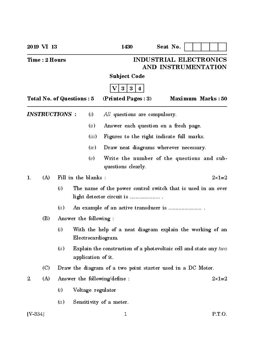
Time : 2 Hours INDUSTRIAL ELECTRONICS
AND INSTRUMENTATION
Subject Code
V 3 3 4
Total No. of Questions : 5 (Printed Pages : 3) Maximum Marks : 50
INSTRUCTIONS : (i) All questions are compulsory.
(ii) Answer each question on a fresh page.
(iii) Figures to the right indicate full marks.
(iv) Draw neat diagrams wherever necessary.
(v) Write the number of the questions and sub-
questions clearly.
1. (A) Fill in the blanks : 2×1=2
(i) The name of the power control switch that is used in an over
light detector circuit is ..................... .
(ii) An example of an active transducer is ....................... .
(B) Answer the following :
(i) With the help of a neat diagram explain the working of an
Electrocardiogram.
(ii) Explain the construction of a photovoltaic cell and state any two
application of it.
(C) Draw the diagram of a two point starter used in a DC Motor.
2. (A) Answer the following/define : 2×1=2
(i) Voltage regulator
(ii) Sensitivity of a meter.
Page 2
(i) With the help of a neat block diagram explain the working of
an inveter.
(ii) State any three point of comparision between RF signal generator
and AF signal generator.
(C) Answer the following in short : 1×2=2
State the two types of speed control method used in a DC shunt
motor.
3. (A) Fill in the blanks : 1×2=2
(i) The type of semiconductor material that is used in an IRLED
is ................ .
(ii) The ratio of change in the output voltage with the change in
load current is known as ...................... .
(B) Answer the following : 3×1=3
Draw a neat block diagram of CRO and state the function of verfical
amplifier and delay line.
(C) Answer the following in detail : 5
(i) Draw the functional block diagram of timer IC 555 and epxlain.
Or
(ii) With a neat circuit diagram explain the working of monostable
multivibrator using timer IC 555.
4. (A) Answer the following in one sentence/word : 2
(i) Name the electronic component whose resistance changes with
the change in temperature.
(ii) State the output time equation of an Astable Multivibrator using
timer IC 555.
Page 3
With a neat Circuit diagram explain range extension of a voltmeter.
(C) Answer the following in detail (any one) : 5×1=5
(i) Define a resistive transducer. With a neat diagram explain any
one type of a strain gauge transducer.
Or
(ii) Define a capacitive transducer. With a neat diagram explain the
working of a microphone as a capacitive transducer.
5. Answer the following in short : 2×5=10
(i) Draw the circuit diagram of a lamp dimmer constructed using a DIAC
and TRIAC.
(ii) State any two points of comparision between LED and LCD.
(iii) Explain the need of a starter in a DC motor.
(iv) Explain the working of tong tester.
(v) With a neat diagram explain the measurement of time period using
a CRO.
Document Details
| Board / Org | Goa Board |
| Exam | Class 12 |
| Type | Question Paper |
| Pages | 3 |
| Updated | 30 Apr 2026 |