Karnataka 2nd PUC Physics Alternating Current MCQ with Answers
Finished viewing? Save it for later —
Download Karnataka 2nd PUC Physics Alternating Current MCQ with Answers (PDF · 17 pages)About Karnataka 2nd PUC Physics Alternating Current MCQ with Answers
Karnataka 2nd PUC Physics Alternating Current MCQ with Answers is available here for free download. Published by Karnataka Board for Class 12, this question bank can be viewed online or downloaded as a PDF (17 pages). Candidates preparing for Class 12 can use Karnataka 2nd PUC Physics Alternating Current MCQ with Answers to understand the exam pattern, the type of questions asked, and the overall difficulty level.
Frequently Asked Questions
How can I download Karnataka 2nd PUC Physics Alternating Current MCQ with Answers?
Open this page and click the Download button to save Karnataka 2nd PUC Physics Alternating Current MCQ with Answers as a PDF. It is completely free on AglaSem Docs.
Is Karnataka 2nd PUC Physics Alternating Current MCQ with Answers free to download?
Yes. Karnataka 2nd PUC Physics Alternating Current MCQ with Answers can be viewed online and downloaded as a PDF free of cost on AglaSem Docs.
How many pages does Karnataka 2nd PUC Physics Alternating Current MCQ with Answers have?
Karnataka 2nd PUC Physics Alternating Current MCQ with Answers contains 17 pages, which you can read online or download together as a single PDF.
Where can I find more Class 12 study material?
You can find more Class 12 question papers, sample papers, syllabus, and answer keys on AglaSem Docs.
Karnataka 2nd PUC Physics Alternating Current MCQ with Answers – Text
Read the full text of this question bank below — useful to quickly search, copy and reference the content online without downloading the PDF.
📄 View text version (17 pages)
Page 1
DEPARTMENT OF SCHOOL EDUCATION (PRE-UNIVERSITY)
18TH CROSS, MALLESHWARAM, BENGALURU – 560 012
CHAPTER-WISE MULTIPLE-CHOICE QUESTIONS FOR COMPETITIVE EXAM
SUBJECT: PHYSICS - II PUC
NAME OF THE CHAPTER: CHAPTER – 7: ALTERNATING CURRENT
SYNOPSIS
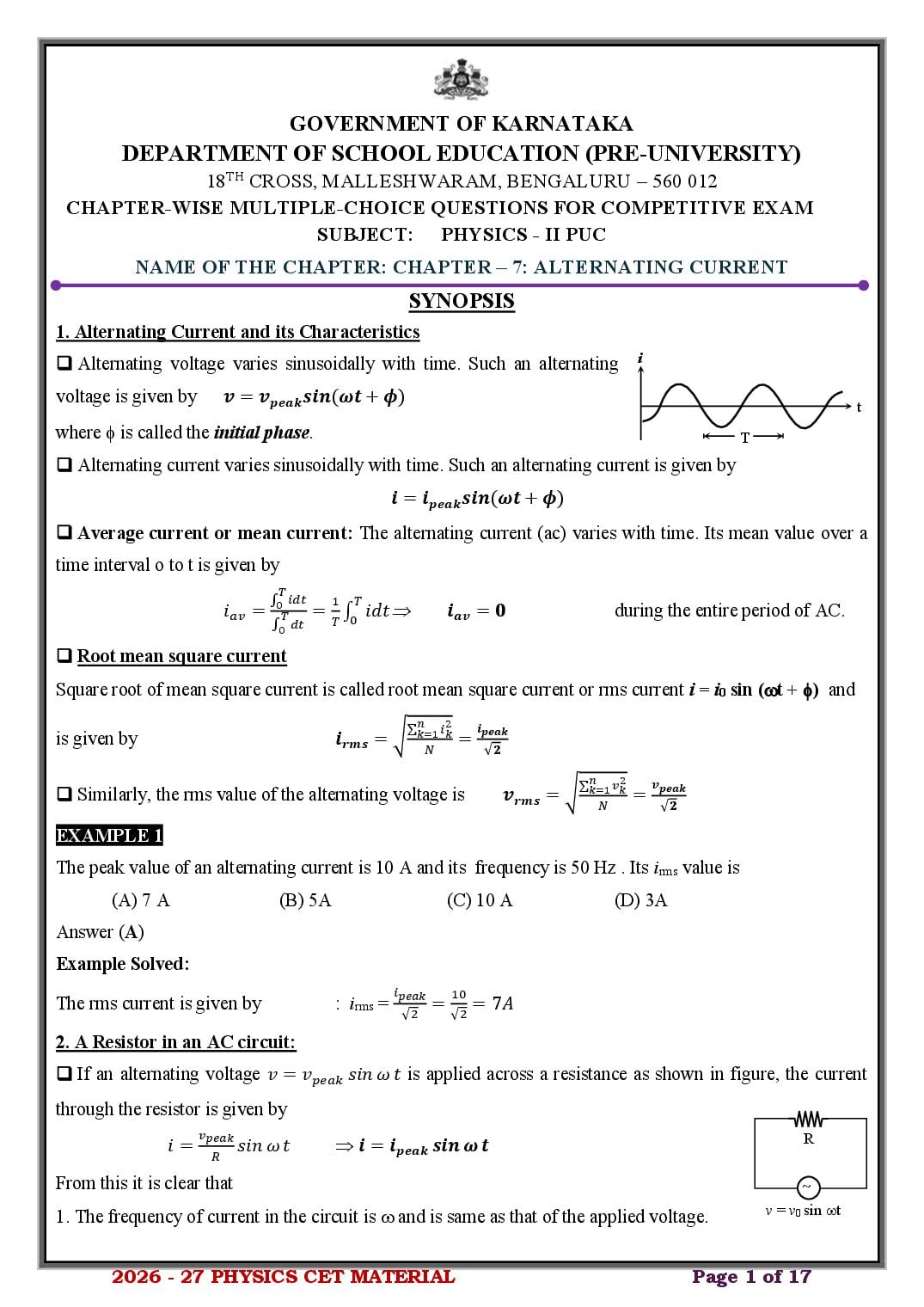
1. Alternating Current and its Characteristics
❑ Alternating voltage varies sinusoidally with time. Such an alternating i
voltage is given by 𝒗 = 𝒗𝒑𝒆𝒂𝒌 𝒔𝒊𝒏(𝝎𝒕 + 𝝓)
t
where is called the initial phase. T
❑ Alternating current varies sinusoidally with time. Such an alternating current is given by
𝒊 = 𝒊𝒑𝒆𝒂𝒌 𝒔𝒊𝒏(𝝎𝒕 + 𝝓)
❑ Average current or mean current: The alternating current (ac) varies with time. Its mean value over a
time interval o to t is given by
𝑇
∫0 𝑖𝑑𝑡 1 𝑇
𝑖𝑎𝑣 = 𝑇 = 𝑇 ∫0 𝑖𝑑𝑡 𝒊𝒂𝒗 = 𝟎 during the entire period of AC.
∫0 𝑑𝑡
❑ Root mean square current
Square root of mean square current is called root mean square current or rms current i = i0 sin (t + ) and
∑𝑛 𝑖2 𝒊
is given by 𝒊𝒓𝒎𝒔 = √ 𝑘=1 𝑘
= 𝒑𝒆𝒂𝒌
𝑁 √𝟐
∑𝑛 𝑣2 𝒗𝒑𝒆𝒂𝒌
❑ Similarly, the rms value of the alternating voltage is 𝒗𝒓𝒎𝒔 = √ 𝑘=1 𝑘
=
𝑁 √𝟐
EXAMPLE 1
The peak value of an alternating current is 10 A and its frequency is 50 Hz . Its irms value is
(A) 7 A (B) 5A (C) 10 A (D) 3A
Answer (A)
Example Solved:
𝑖 10
The rms current is given by : irms = 𝑝𝑒𝑎𝑘 = = 7𝐴
√2 √2
2. A Resistor in an AC circuit:
❑ If an alternating voltage 𝑣 = 𝑣𝑝𝑒𝑎𝑘 𝑠𝑖𝑛 𝜔 𝑡 is applied across a resistance as shown in figure, the current
through the resistor is given by
𝑣 R
𝑖 = 𝑝𝑒𝑎𝑘
𝑅
𝑠𝑖𝑛 𝜔 𝑡 𝒊 = 𝒊𝒑𝒆𝒂𝒌 𝒔𝒊𝒏 𝝎 𝒕
From this it is clear that ~
v = v0 sin t
1. The frequency of current in the circuit is and is same as that of the applied voltage.
2026 - 27 PHYSICS CET MATERIAL Page 1 of 17
Page 2
3. Current in the circuit is independent of frequency and decreases with increase in R (similar to that in dc
circuits)
EXAMPLE 2
The instantaneous voltage across a resistor of resistance R connected across an AC source and instantaneous
current through it are given by v = (10 V) sin t and i = (2 A) sin (t + ). Then the value of resistance of the
resistor and respectively are
(A) 2 , 30 (B) 5 , 30 (C) 5 , 0 (D) 10 , 60
Answer (C)
Example Solved:
Compare the relations for instantaneous current
and voltage in purely resistive circuit : irms = 𝑣 = 𝑣𝑝𝑒𝑎𝑘 𝑠𝑖𝑛 𝜔 𝑡𝑎𝑛𝑑 𝑖 = 𝑖𝑝𝑒𝑎𝑘 𝑠𝑖𝑛 𝜔 𝑡
with : v = (10 V) sin t and i = (2 A) sin (t + )
we get : vpeak = 10 V and ipeak = 2 A
𝑣 10
Thus, the resistance in the circuit : R = 𝑖 𝑝𝑒𝑎𝑘 = 2 = 5 𝛺
𝑝𝑒𝑎𝑘
and : = 0.
3. An inductor in an AC circuit L
❑ If an emf v = vpeak sin t is applied across an inductor of inductance L as shown,
𝜋
The current through the inductor is 𝑖 = 𝑖𝑝𝑒𝑎𝑘 𝑠𝑖𝑛 (𝜔𝑡 − 2 ) with
~
𝒗𝒑𝒆𝒂𝒌
𝒊𝒑𝒆𝒂𝒌 = v = vpeak sin t
𝝎𝑳
From this expression it is evident that
❑ The frequency of current in the circuit is same as that of applied emf but current in an inductor ‘lags’ the
applied voltage by (/2) [or voltage leads the current by (/2)]
❑ This quantity is referred to as ‘inductive-reactance’ and is represented by XL and represents the opposition
of a coil to ac, i.e., 𝑿𝑳 = 𝝎𝑳 = 𝟐𝝅𝝂𝑳
EXAMPLE 3
Which among the following graphs correctly represents the variation of inductive reactance for a given
inductor with the frequency of applied source?
XL XL XL XL
B B B (D) B
(A) (B) (C)
Answer (A)
2026 - 27 PHYSICS CET MATERIAL Page 2 of 17
Page 3
From the expression for the inductive reactance : XL = 2L XL
This is similar to the variation of y vs x in : y = mx
Hence the graph is a : straight line as in choice (A)
4. A capacitor in an AC circuit
❑ If v = vpeak sin t is applied across a capacitor as shown,
C
𝝅
The current ’through’ the capacitor is 𝒊 = 𝒊𝒑𝒆𝒂𝒌 𝒔𝒊𝒏 (𝝎𝒕 + 𝟐 )
𝒗𝒑𝒆𝒂𝒌 ~
with 𝒊𝒑𝒆𝒂𝒌 = 𝟏
v = vpeak sin t
𝝎𝑪
From this expression it is evident that
❑ The frequency of current in the circuit is same as that of applied emf but current in an capacitor leads the
applied voltage by (/2) [or voltage lags behind the current by (/2)]
❑ This quantity is referred to as ‘capacitive-reactance’ and is represented by XC and represents the opposition
𝟏 𝟏
offered by a capacitor to ac, i.e., 𝑿𝑪 = 𝝎𝑪 = 𝟐𝝅𝝂𝑪
EXAMPLE 4
Which among the following graphs correctly represents the variation of capacitive reactance for a given
capacitor with the frequency of applied source?
XC XC XC XC
B B B (D) B
(A) (B) (C)
Answer (D)
Example Solved:
1 1
From the expression for the capacitive reactance : 𝑋𝐶 = 2𝜋𝜈𝐶 ⇒ 𝑋𝐶 ∝ 𝜈
𝐶
This is similar to the variation of y vs x in :y=𝑥
Hence the graph is a : rectangular hyperbola as in choice (D)
5. Series LCR circuit:
❑ In the case of a series LCR circuit, an inductor, a capacitor and a resistor are connected in series with an
AC source.
1
❑ The resultant of the reactances 1/C and L, i.e., 𝑋 = 𝑋𝑐 − 𝑋𝐿 = (𝜔𝐶 − 𝜔𝐿) is along the positive y-axis
1
❑ The resultant of R and the reactance (𝜔𝐶 − 𝜔𝐿) which has a magnitude called the impedance of series
𝟏 𝟐
LCR circuit given by 𝒁 = √𝑹𝟐 + (𝝎𝑪 − 𝝎𝑳) . This is the impedance of the circuit.
2026 - 27 PHYSICS CET MATERIAL Page 3 of 17
Page 4
ipeak
𝜔𝐶
C vpeak, C
L R
vpeak ipeak Z
1
vpeak, L-C ipeak ( − 𝜔𝐿)
𝜔𝑐
~
vpeak sin t ipeak
vpeak, R ipeak R
vpeak, L ipeak L
𝟏
−𝝎𝑳 𝑿𝑳 −𝑿𝑪
❑ This resultant makes an angle with the x-axis given by 𝒕𝒂𝒏 = 𝝎𝑪
⇒ 𝒕𝒂𝒏 = .
𝑹 𝑹
is the phase angle by which the current leads the voltage.
𝒗𝒑𝒆𝒂𝒌
❑ The current in the series LCR circuit is given by 𝒊 = 𝟐
𝒔𝒊𝒏( 𝝎𝒕 + 𝝋)
√𝑹𝟐 +( 𝟏 −𝝎𝑳)
𝝎𝑪
EXAMPLE 5
An LCR series circuit having L = 100 mH, C = 100 F, R = 120 has an ac source of voltage
v = (30 V) sin (100) t; where t is in second. The impedance of the circuit is
(A) 90 (B) 120 (C) 150 (D) 210
Answer (C)
Example Solved:
1
The reactance of the circuit is : 𝑋𝐿𝐶 = 𝜔𝐶 − 𝜔𝐿
1
Or : XLC = (100)(100×10−6 ) − (100) × (100 × 10−3 ) = 90𝛺
Given that R = 120 , the impedance is : 𝑍 = √𝑅 2 + 𝑋 2 = √(120)2 + (90)2 = 150𝛺
6. Resonance in series LCR circuit
𝟏 𝟐
❑ The impedance (Z) of a series LCR circuit is given by 𝒁 = √𝑹𝟐 + (𝝎𝑳 − 𝝎𝑪) .
❑ At very low frequencies, inductive reactance XL = L can be neglected, but capacitive reactance
(XC = 1/ C) is considerable.
❑ As frequency of alternating voltage applied to the circuit is increased, XL goes on increasing and XC goes
on decreasing.
1 𝟏
❑ For a particular value of (= r, say) we have XL = XC i.e., rL = 𝜔 𝐶 𝝎𝒓 =
𝑟 √𝑳𝑪
1
Or 𝜈𝑟 = 2𝜋√𝐿𝐶
ipeak
which is called the resonant frequency of series LCR
𝑖𝑝𝑒𝑎𝑘,𝑚𝑎𝑥 R = 10
circuit
R decreases
❑ At this particular frequency fr, as XL = XC, therefore, 𝑖𝑝𝑒𝑎𝑘 = 𝑖𝑝𝑒𝑎𝑘,𝑚𝑎𝑥
√2 Q increases
from (1) the impedance becomes 𝑍 = √𝑅 2 + 0 = 𝑅 R = 100
When impedance of RLC circuit is minimum the current
𝑣 𝑣
𝑖𝑝𝑒𝑎𝑘 = 𝑝𝑒𝑎𝑘 = 𝑝𝑒𝑎𝑘 becomes maximum. O (Hz)
LC r UC
𝑍 𝑅
2026 - 27 PHYSICS CET MATERIAL Page 4 of 17
Page 5
is clear that for frequencies greater than or less than r the values of current are less than the maximum value
ipeak of the current.
❑ Further, when = r, maximum current is inversely proportional to R.
❑ For lower R values, ipeak is large and vice-versa.
EXAMPLE 6
In a series LCR circuit, the current at resonance frequency depends on the
(A) capacitance value (B) inductance value
(C) resistance value (D) both the inductance and capacitance values
Answer (C)
7. Quality factor or sharpness of resonance (Not required for KCET)
❑ The Q factor of series LCR resonant circuit is the ratio of the voltage developed across the inductance or
capacitance at resonance to the impressed voltage, which is the voltage applied across R. 𝑄 =
𝑣𝑜𝑙𝑡𝑎𝑔𝑒 𝑎𝑐𝑟𝑜𝑠𝑠 𝐿 𝑜𝑟 𝐶 𝑟𝑒𝑠𝑜𝑛𝑎𝑛𝑡 𝑓𝑟𝑒𝑞𝑢𝑒𝑛𝑐𝑦 𝝎𝒓 𝝂𝒓
❑ 𝑸= =𝝎 =𝝂
𝑎𝑝𝑝𝑙𝑖𝑒𝑑 𝑣𝑜𝑙𝑡𝑎𝑔𝑒 𝑏𝑎𝑛𝑑 𝑤𝑖𝑑𝑡ℎ 𝑼𝑪 −𝝎𝑳𝑪 𝑼𝑪 −𝝂𝑳𝑪
𝟏 𝑳
❑ In terms of L, C and R, we have 𝑸 = 𝑹 √𝑪
❑ As R is increased, Q factor of the circuit should decrease.
❑ The values of Q usually vary from 10 to 100. However, there are electronic circuits which may have
Q = 200.
EXAMPLE 7
In a series LCR circuit, the Q factor can be increased by
(A) increasing L (B) decreasing R (C) decreasing C (D) all the above.
Answer (D)
8. Power in AC Circuits
❑ The average power delivered by the source is,
𝟏 𝒗𝒑𝒆𝒂𝒌 𝒊𝒑𝒆𝒂𝒌
𝑷𝒂𝒗 = 𝒗𝒑𝒆𝒂𝒌 × 𝒊𝒑𝒆𝒂𝒌 × 𝒄𝒐𝒔 𝝓 = ( )( ) (𝒄𝒐𝒔 𝝓)
𝟐 √𝟐 √𝟐
That is 𝑷𝒂𝒗 = 𝒗𝒓𝒎𝒔 × 𝒊𝒓𝒎𝒔 × 𝒄𝒐𝒔𝝓
❑ The term cos is called the power factor for the circuit.
❑ For a purely resistive circuit, = 0 so that cos = 1 and P = vrmsirms.
𝜋
❑ For purely reactive circuits (no resistance, only capacitance and /or inductance), 𝜙 = 2 Or 𝜙 = −𝜋/2.
❑ In these cases, cos = 0 and hence no power is absorbed in such circuits.
❑ Wattless current: The current flowing in a circuit with pure inductance and capacitance but with zero
resistance, results in zero power consumption and hence called wattles current.
2026 - 27 PHYSICS CET MATERIAL Page 5 of 17
Page 6
Power factor is unity in an AC circuit containing a/an
(A) pure resistor (B) pure capacitor
(C) series L, C and R at resonance frequency (D) both (1) and (3)
Answer (D)
10. Transformers:
❑ A transformer is a device to step-up or step-down ac voltage. IP IS
❑ It works on the principle of mutual induction.
NP NS VS
❑ A transformer consists of two coils of insulated wire wound VP
separately over a laminated iron core.
❑ The ac voltage to be altered is fed to the primary and the altered ac voltage is obtained across the secondary.
❑ When an alternating current flows in the primary, it sets up a changing magnetic flux which gets linked
with the secondary.
❑ Let NS and NP be the number of turns in the secondary and the primary respectively.; Then
𝑽𝑺 𝑵
= 𝑵 𝑺 = 𝒇𝑻 where fT = turns ratio of the transformer
𝑽𝑷 𝑷
❑ For a step-up transformer, ft > 1 as NS >NP. Hence VS > VP.
❑ For a step-down transformer, ft < 1 as NS < NP. Hence VS < VP.
𝑰𝑷 𝑵
❑ In terms of currents = 𝑵 𝑺 = 𝒇𝑻 .
𝑰𝑺 𝑷
❑ Energy loss in a transformer
In a transformer, there will be loss of energy due to several reasons.
1. Loss of energy due to resistance of the windings. 2. Flux Leakage.
3. Hysteresis loss. 4. Eddy currents losses.
EXAMPLE 10
Soft iron core used in a transformer decreases the energy loss due to
(A) flux leakage (B) hysteresis (C) heating (D) eddy current.
Answer (B)
9. LC oscillations (Not required for KCET)
❑ The principle of conservation of energy leads to UL + UC = constant L
1 1 𝑞2
That is 𝐿𝑖 2 + 2 𝐶 = 𝑐𝑜𝑛𝑠 𝑡𝑎𝑛 𝑡
2
𝑑 1 1 𝑞2
Since Utot = constant ( 𝐿𝑖 2 + 2 𝐶 ) = 0
𝑑𝑡 2
C
𝑑𝑖 1 𝑑𝑞 𝑑2 𝑞 1 𝑑𝑞 𝑑2 𝑞 1
Or 𝐿𝑖 𝑑𝑡 + 𝐶 𝑞 𝑑𝑡 = 0 ⇒ 𝐿𝑖 𝑑𝑡 2 + 𝐶 𝑞 𝑑𝑡 = 0 ⇒ 𝑑𝑡 2 + (𝐿𝐶) 𝑞 = 0
𝟏
❑ Thus the charge in the circuit oscillates simple harmonically at a frequency 𝝂𝑳𝑪 = 𝟐𝝅√𝑳𝑪
EXAMPLE 9
The electrical analogue of a spring constant k is
(A) L (B) 1/L (C) C (D) 1/C
❑ Answer (D)
2026 - 27 PHYSICS CET MATERIAL Page 6 of 17
Page 7
Mechanical system Electrical system
L
v k i
q
x
C
1. Displacement, 𝑥 Electric charge, 𝑞
𝑑𝑥 𝑑𝑞
2. Velocity, 𝑣 = 𝑑𝑡 Electric current, 𝑖 = 𝑑𝑡
𝑑2 𝑥 𝑑2 𝑞
3. Acceleration, 𝑎 = 𝑑𝑡 2 Rate of variation of electric current 𝑖̇ = 𝑑𝑡 2
𝑑2𝑥 𝑘 𝑑2 𝑞 1
4. + 𝑥=0 + ( )𝑞 = 0
𝑑𝑡 2 𝑚 𝑑𝑡 2 𝐿𝐶
1 𝑘 1 1
5. Frequency of oscillation, 𝜈 = 2𝜋 √𝑚 Frequency of oscillation, 𝜈 = 2𝜋 √𝐿𝐶
6. Mass, 𝑚 Inductance, 𝐿
1
7. Spring constant, 𝑘 Inverse of capacitance, 𝐶
1 1
8. K.E. stored in mass = 2 𝑚𝑣 2 Magnetic energy stored in the inductor 2 𝐿𝑖 2
1 1 𝑞2
9. PE stored in spring = 2 𝑘𝑥 2 Electrostatic energy stored in the capacitor 2 𝐶
Instantaneous displacement, x = A sin t Instantaneous charge, q = q0 sin t
10.
11. Instantaneous velocity, v = A cos t Instantaneous current in the inductor i = q0 cos t
12. Maximum velocity of the mass = A Maximum current in the inductor = q0
The law of conservation of energy: The law of conservation of energy:
13. 1 1 1 1 𝑞2
𝑚𝑣 2 + 2 𝑘𝑥 2 = 𝑐𝑜𝑛𝑠 𝑡𝑎𝑛 𝑡 𝐿𝑖 2 + 2 𝐶 = 𝑐𝑜𝑛𝑠 𝑡𝑎𝑛 𝑡
2 2
2026 - 27 PHYSICS CET MATERIAL Page 7 of 17
Page 8
1. When the current changes continuously in magnitude and periodically in direction, several times per
second, the current is known as the
(A) direct current (B) induced current
(C) displacement current (D) alternating current
2. What is the average value of the AC voltage over one complete cycle?
2𝑉𝑚𝑎𝑥 𝑉
(A) Zero (B) Vmax (C) (D) 𝑚𝑎𝑥
𝜋 2
3. Which of the following graphs shows, in a pure resistor, the voltage and current are in phase?
(A) (C)
(C) (D)
4. In an AC circuit, 𝑖 = 100 sin(200𝜋𝑡). The time required for the current to achieve its peak value will be
1 1 1 1
(A) 100 𝑠 (B) 200 𝑠 (C) 300 𝑠 (D) 400 𝑠
𝑣𝑚
5. Current through a circuit is given by 𝑖 = 𝜔𝐿 cos(𝜔𝑡) + 𝑐𝑜𝑛𝑠𝑡𝑎𝑛𝑡, in the given equation the integration
constant has the dimension of
(A) resistor (B) current (C) voltage (D) inductor
𝑣𝑚
6. 𝑖 = 𝜔𝐿 cos(𝜔𝑡) + 𝑐𝑜𝑛𝑠𝑡𝑎𝑛𝑡, the integration constant in the given equation is
(A) time-independent (B) time-dependent
(C) may be time-independent (D) never time dependent
7. In a purely inductive AC circuit, the current reaches its maximum value later than the voltage by
(A) one-fourth of a period (B) half of a period
(C) three by fourth of a period (D) complete a period
8. In an AC circuit, the current lags behind the voltage by π/2. The components of the circuit are
(A) 𝑅 𝑎𝑛𝑑 𝐿 (B) 𝐿 𝑎𝑛𝑑 𝐶 (C) 𝑅 𝑎𝑛𝑑 𝐶 (D) only 𝑅
9. When an AC voltage of 220 V is applied to the capacitor C
(A) The maximum voltage between plates is 220 V
(B) The current is in phase with the applied voltage
(C) The charge on the plates is in phase with the applied voltage
(D) Power delivered to the capacitor is zero
2026 - 27 PHYSICS CET MATERIAL Page 8 of 17
Page 9
10. Which of the following diagram shows that the current phasor 𝐼, is 2 ahead of the voltage phasor 𝑉 as they
rotate counter-clockwise?
11. An alternating voltage 𝑣 = 200√2 sin(100𝑡) is connected to a 1µ𝐹, capacitor through an AC ammeter.
The reading of the ammeter shall be
(A) 10 mA (B) 20 mA (C) 40 mA (D) 80 mA
12. Which of the following graph is correct for a series 𝐿 − 𝐶 − 𝑅 𝑐𝑖𝑟𝑐𝑢𝑖𝑡 for 𝑋𝐶 > 𝑋𝐿 ?
(A) (B) (C) (D)
13. In an series 𝐿 − 𝐶 − 𝑅 AC circuit, then voltage across each of the components 𝐿, 𝐶 𝑎𝑛𝑑 𝑅 is 50 𝑉. The
voltage across the 𝐶 − 𝑅 combination will be
(A) 50 𝑉 (B) 50√2 𝑉 (C) 100 𝑉 (D) zero
14. As the frequency of an AC circuit increases, the current first increases and then decreases. What
combination of circuit elements is most likely to comprise the circuit?
(A) Inductor and capacitor (B) Resistor and inductor
(C) Resistor and capacitor (D) Resistor, inductor and capacitor
15. In an series 𝐿 − 𝐶 − 𝑅 AC circuit, then voltage across each of the components 𝐿, 𝐶 𝑎𝑛𝑑 𝑅 is 50 𝑉. The
voltage across the 𝐿 − 𝑅 combination will be
(A) 50 𝑉 (B) 50√2 𝑉 (C) 100 𝑉 (D) zero
16. Figure shows the variation of 𝑖𝑚 with 𝜔 in a
(A) R-L-C circuit
(B) R-L circuit
(C) R-C circuit
(D) L-C circuit
17. A capacitor and an inductance coil are connected in separate AC circuits with and bulb glowing in both the
circuits. The bulb glows more brightly when
(A) the number of turns in the inductance coil
(B) an iron rod is introduced into the inductance coil
(C) a dielectric is introduced into the gap between the plates of the capacitor
(D) Separation between the plates of the capacitor is increased
2026 - 27 PHYSICS CET MATERIAL Page 9 of 17
Page 10
(A) the tuning mechanism of a radio (B) the tuning mechanism of TV set
(C) Both radio and TV tuning circuits (D) mobile network tuner
19. In an L-C-R circuit, capacitance is changed from 𝐶 𝑡𝑜 2𝐶.For the resonant frequency to remain
unchanged, the inductance should be change from L to
𝐿 𝐿
(A) 4𝐿 (B) 2𝐿 (C) 2 (D) 4
20. The potential difference 𝑉 and the current 𝑖 flowing through an instruments in an AC circuit of frequency
𝜈 are given by 𝑣 = 5 𝑐𝑜𝑠𝜔𝑡 𝑣𝑜𝑙𝑡𝑠 and 𝑖 = 2 𝑠𝑖𝑛𝜔𝑡 𝑎𝑚𝑝𝑒𝑟𝑒 (where,𝜔 = 2𝜋𝜈). The power dissipated in
the instrument is
(A) zero (B) 10 W (C) 5 W (D) 2.5 W
21. Which of the following components of a L-C-R circuit, with AC supply, do not dissipates energy?
(A) L, C (B) R, C (C) L, R (D) L C R
22. The value of emf in the secondary coil of a transformer depends on
(A) the number of turns (B) voltage (C) material used (D) induced flux
23. How much current is drawn by the primary coil of a transformer which steps down 220 V to 22 V to
operate a device with an impedance of 220 Ω?
(A) 1 A (B) 0.25 A (C) 0.01 A (D) 1.50 A
24. When an AC voltage of 220 V is applied to the capacitor C
(A) the maximum voltage between plates is 220 V
(B) the current is in phase with the applied voltage
(C) the charge on the plates is in phase with the applied voltage
(D) power delivered to the capacitor is zero
25. A battery of 10 V is connected to primary of a transformer of ratio is 20. The output across secondary coil
is
(A) 20 V (B) 10 V (C) 5 V (D) zero
26. A resistance of 20 Ω is connected to a source of an alternating voltage, = 220 𝑠𝑖𝑛(100𝜋𝑡) . The time
taken by current to change from its peak value to rms value is
(A) 0.2 𝑠 (B) 0.25 𝑠 (C) 25 × 10 −3 𝑠 (D) 2.5 × 10 −3 𝑠
27. The r.m.s. value of potential difference V shown in the figure is
𝑉0
(A) (B) 𝑉0
√3
𝑉0 𝑉
(C) (D) 20
√2
28. A 100 Ω resistor is connected to a 220 V, 50 Hz AC supply, then the rms value of current in the circuit is
(A) 2.2 A (B) 4.2 A (C) 3.2 A (D) 2.4 A
29. A light bulb is rated at 100 W for a 220 V supply. The resistance of the bulb is
(A) 48 Ω (B) 484 Ω (C) 480 Ω (D) 350 Ω
2026 - 27 PHYSICS CET MATERIAL Page 10 of 17
Page 11
30. The electric current in a circuit is given by 𝑖 = 𝑖0 (𝜏)for same time. The rms current for the period
𝑡 = 0 𝑡𝑜 𝑡 = 𝜏 is
𝑖 𝑖0 𝑖 3
(A) 0 (B) (C) √ 20 (D) 4 √𝑖0
√2 √3
31. An alternating current is given by the equation 𝑖 = 𝑖1 𝑐𝑜𝑠𝜔𝑡 + 𝑖2 𝑠𝑖𝑛𝜔𝑡. The rms current is given by
1 1
1 1 1 1
(A) (𝑖1 + 𝑖2 ) (B) (𝑖1 + 𝑖2 )2 (C) (𝑖1 2 + 𝑖2 2 )2 (D) 2 (𝑖1 2 + 𝑖2 2 )2
√2 √2 √2
32. A resonant AC circuit contains a capacitor of capacitance 10−6 𝐹 and an inductor of 10−4 𝐻. The
frequency of electrical oscillations will be
105 10
(A) 105 𝐻𝑧 (B) 10 𝐻𝑧 (C) 2𝜋 𝐻𝑧 (D) 2𝜋 𝐻𝑧
33. Assertion: In a series R-L-C circuit, the voltages across resistor, inductor and capacitor are 8 V, 16 V
and 10 V, respectively. The resultant emf in the circuit is 10 V.
Reason: Resultant emf of the circuit is given by the relation. √𝑉𝑅2 + (𝑉𝐿 − 𝑉𝐶 )2
(A) Both Assertion and Reason are correct and Reason is the correct explanation of Assertion.
(B) Both Assertion and Reason are correct but Reason is not the correct explanation of Assertion.
(C) Assertion is correct but Reason is incorrect.
(D) Assertion is incorrect but Reason is correct
𝜋
34. Statement I: The current lags behind the emf by a phase angle of 2 , when AC flows through an inductor.
Statement II: The inductive reactance increases as the frequency of AC source decreases.
(A) Both Statement I and II are correct and Statement II is the correct explanation of Statement I.
(B) Both Statement I and II are correct but Statement II is not the correct explanation of Statement I.
(C) Statement I is correct but Statement II is incorrect.
(D) Statement I is incorrect but Statement II is incorrect.
35. In the circuit shown in the figure neglecting source
resistance the voltmeter and ammeter reading
respectively, will be R=30Ω RL=30
(A) 0 V, 3 A
Ω
(B) 150 V, 3 A
(C) 150 V, 6 A XL=30 XC=30
(D) 0 V, 8 A Ω Ω
36. Consider the figure,
Which of the above statements is/are correct?
I. The vertical components of phasor V and I represent the sinusoidally varying quantities V and i.
II. The magnitudes of phasor V and I represent the amplitude so the peak values 𝑉𝑚 𝑎𝑛𝑑 𝑖𝑚 of these
oscillating quantities.
III. The projection of voltage and current phasor on vertical axis, i.e 𝑣𝑚 𝑠𝑖𝑛𝜔𝑡, 𝑖𝑚 𝑠𝑖𝑛𝜔𝑡 respectively
represent the value of voltage and current at that instant.
(A) I and II (B) I and III (C) II and III (D) I, II and III
2026 - 27 PHYSICS CET MATERIAL Page 11 of 17
Page 12
Column I Column II
i. Resistive circuit p. No power is dissipated
ii. Purely inductive or capacitive circuit q. Maximum power dissipated as XL=XC
iii. L-C-R series circuit r. Power dissipated only in the resistor.
iv. Power dissipated at resonance in L-C-R circuit s. Maximum power dissipated
(A) i-p ii -q iii -r iv –s (B) i-r ii-p iii-r iv-q
(C) i-r ii-p iii-s iv-q (D) i-q ii-p iii-r iv-s
38. A coil of inductive reactance 31 has a resistance of 8 . It is placed in series with a condenser of
capacitive reactance 25 . The combination is connected to an a.c. source of 110 volt. The power
factor of the circuit is
(A) 0.64 (B) 0.80 (C) 0.33 (D) 0.56
39. In an alternating current circuit consisting of elements in series, the current increases on increasing the
frequency of supply. Which of the following elements are likely to constitute the circuit?
(A) Only resistor (B) Resistor and an inductor
(C) Resistor and a capacitor (D) Only a capacitor
40. An inductor L and a capacitor C are connected in the circuit as shown L in
the figure. The frequency of the power supply is equal to the A1
resonant frequency of the circuit. Which ammeter will read
zero ampere C
A2
(A) 𝐴1
(B) 𝐴2
(C) 𝐴3 A3
(D) Both 𝐴1 and 𝐴2 E = E0 sint
41. A bulb and a capacitor are connected in series to a source of alternating current. If its frequency is
increased, while keeping the voltage of the source constant, then
(A) Bulb will give more intense light
(B) Bulb will give less intense light
(C) Bulb will give light of same intensity as before
(D) Bulb will stop radiating light
42. Which of the following plots may represent the reactance
of a series LC combination?
(A) 𝐼
(B) 𝐼𝐼
(C) 𝐼𝐼𝐼
(D) 𝐼𝑉
2026 - 27 PHYSICS CET MATERIAL Page 12 of 17
Page 13
frequency of the source is adjusted to be less than the resonant frequency (ν < νo), then the phase difference
between the circuit current and the applied voltage is such that:
(A) the voltage leads the current by 90°
(B) the voltage leads the current by a phase angle ϕ (0 < ϕ < 90°)
(C) the current leads the voltage by a phase angle ϕ (0 < ϕ < 90°)
(D) the current and voltage remain completely in phase with each other
44. A circuit element in connected to an alternating voltage supply of variable frequency. When the frequency
is increased, current in the circuit is found to remain same. The circuit element is
(A) capacitor only (B) resistor only
(C) inductor only (D) either a capacitor or an inductor
45. The reactance of a capacitor is 𝑋1 for frequency 𝜔1 and 𝑋2 for frequency 𝜔2 then 𝑋1 : 𝑋2 is
(A) 1: 1 (B) 𝜔1 : 𝜔2 (C) 𝜔2 : 𝜔1 (D) 𝜔12 : 𝜔22
46. An alternating voltage (in volt) given by V = 200 2 sin (100t) is connected to 1 F capacitor through an
AC ammeter. The reading of the ammeter will be
(A) 10 mA (B) 20 mA (C) 40 mA (D) 80 mA
47. A transformer is used to light a 100 W and 110 V lamp from a 220 V mains. If the main current is 0.5 A.
The efficiency of the transformer is approximately
(A) 30% (B) 50% (C) 90% (D) 10%
48. An inductor (L) and resistance (R) are connected in series with an AC source. The phase difference
between voltage (V) and current (I) is 45°. Now a capacitor (C) is connected in series with L-R, If the
phase difference between V and i remain same, then capacitive reactance and impedance of L-C-R circuit
will be-
(A) 𝑅, 2𝑅 (B) 2𝑅, √2 𝑅 (C) 𝑅, 𝑅 (D) 2𝑅, 𝑅
49. In an AC circuit, the power factor
(A) is unity when the circuit is purely resistive.
(B) is unity when the circuit is purely inductive.
(C) is zero when the circuit is purely capacitive.
(D) is 0.5 when the difference of inductive reactance and capacitive reactance is 1.732 times the
resistance.
1
50. In pure inductive circuit, the curves between frequency f and inductive reactance 𝑋 is:
𝐿
(A) (B) (C) (D)
2026 - 27 PHYSICS CET MATERIAL Page 13 of 17
Page 14
1 2 3 4 5 6 7 8 9 10
D A C D B A A A D C
11 12 13 14 15 16 17 18 19 20
B D B D B A C C C A
21 22 23 24 25 26 27 28 29 30
A A C D D D C A B B
31 32 33 34 35 36 37 38 39 40
C C A C A D C B C C
41 42 43 44 45 46 47 48 49 50
A D C B C B C B A B
2026 - 27 PHYSICS CET MATERIAL Page 14 of 17
Page 15
1. In the given circuit the peak voltage across C, L and R are 30 V, 110 V and
60 V respectively. The rms value of the applied voltage is [KCET-2020]
(A) 220 V (B) 70.7 V
(C) 141 V (D) 100 V
1
2. The power factor of R-L circuit is . If the inductive reactance is 2 Ω, the value of resistance is [2020]
√3
1
(A) √2 Ω (B) 0.5 Ω (C) Ω (D) 2 Ω
√2
3. In the given circuit, the resonant frequency is [KCET-2020]
(A) 159.2 𝐻𝑧
(B) 1592 𝐻𝑧
(C) 15910 𝐻𝑧
(D) 15.92 𝐻𝑧
4. What will be the reading in the voltmeter and ammeter of the circuit shown? [KCET-2021]
(A) 90 V, 2 A
(B) 0 V, 2 A
(C) 90 V, 1 A
(D) 0 V, 1 A
5. LC oscillations are similar and analogous to the mechanical oscillations of a block attached to a spring.
The electrical equivalent of the force constant of the spring is [KCET-2021]
(A) reciprocal of capacitive reactance (B) capacitive reactance
(C) reciprocal of capacitance (D) capacitance
6. In an oscillating LC circuit, 𝐿 = 3.00 𝑚𝐻 and 𝐶 = 2.70 𝜇𝐹. At 𝑡 = 0 the charge on the capacitor is zero
and the current is 2.00 𝐴. The maximum charge that will appear on the capacitor will be [KCET-2021]
(A) 1.8 × 10⁻⁵ 𝐶 (B) 18 × 10−5 𝐶 (C) 9 × 10⁻⁵ 𝐶 (D) 90 × 10−5 𝐶
7. An alternating current is given by 𝑖 = 𝑖1 sin 𝜔𝑡 + 𝑖2 cos 𝜔𝑡. The rms current is given by [KCET-2022]
𝑖 2 +𝑖 2 𝑖 2 +𝑖2 2 𝑖 +𝑖2 𝑖 −𝑖2
(A) √ 1 2 2 (B) √ 1 (C) 1 (D) 1
√2 √2 √2
8. A fully charged capacitor C with initial charge 𝑞0 is connected to a coil of self-inductance L at 𝑡 = 0. The
time at which the energy is stored equally between the electric and the magnetic field is [KCET-2022]
𝜋
(A) 𝜋√𝐿𝐶 (B) √𝐿𝐶 (C) 2𝜋√𝐿𝐶 (D) √𝐿𝐶
4
9. A series resonant ac circuit contains a capacitance 10−6 𝐹 and an inductor of 10−4 𝐻. The frequency of
electric oscillations will be [KCET-2022]
105 10
(A) 2𝜋 𝐻𝑧 (B) 2𝜋 𝐻𝑧 (C) 105 𝐻𝑧 (D) 10 𝐻𝑧
10. In series LCR circuit at resonance, the path difference between voltage and current is [KCET-2023]
𝜋
(A) 𝜋 (B) 4 (C) 𝜋/2 (D) 𝑧𝑒𝑟𝑜
11. An ideal transformer has a turns ratio of 10. When the primary is connected to 220 V, 50 Hz ac source,
the power output is [KCET-2023]
1 𝑡ℎ
(A) 10 the power input (B) equal to power input
(C) zero (D) 10 times the power input
2026 - 27 PHYSICS CET MATERIAL Page 15 of 17
Page 16
frequency of the AC source connected to it as shown in the
graph. The quality factor Q of the series LCR circuit is [2023]
(A) 2.5
(B) 5
(C) 1
(D) 0.4
13. Which of the following combinations should be selected for better tuning of an LCR circuit used for
communication? [KCET-2024]
(A) 𝑅 = 20 Ω, 𝐿 = 1.5 𝐻, 𝐶 = 35 𝜇𝐹 (B) 𝑅 = 25 Ω, 𝐿 = 2.5 𝐻, 𝐶 = 45 𝜇𝐹
(C) 𝑅 = 25 Ω, 𝐿 = 1.5 𝐻, 𝐶 = 45 𝜇𝐹 (D) 𝑅 = 15 Ω, 𝐿 = 3.5 𝐻, 𝐶 = 30 𝜇𝐹
14. In an LCR series circuit, the value of only capacitance C is varied. The resulting variation of resonance
frequency 𝑓0 as a function of C can be represented as [EX][KCET-2024]
15. The figure shows variation of R, 𝑋𝐿 and 𝑋𝐶 with frequency f
in a series LCR circuit. Then for what frequency point is the
circuit capacitive? [KCET-2024]
(A) 𝐵
(B) 𝐷
(C) 𝐴
(D) 𝐶
16. In domestic electric mains supply, the voltage and the current are [KCET-2025]
(A) AC voltage and AC current (B) AC voltage and DC current
(C) DC voltage and DC current (D) DC voltage and AC current
17. A sinusoidal voltage produced by an AC generator at any instant is given by an equation 𝑉 =
315 sin 314𝑡. The rms value of voltage and frequency are respectively [KCET-2025]
(A) 200 V, 100 Hz (B) 200 V, 50 Hz (C) 220 V, 100 Hz (D) 220 V, 50 Hz
18. A series LCR circuit containing an AC source of 100 V has an inductor and a capacitor of reactances 24
Ω and 16 Ω respectively. If a resistance of 6 Ω is connected in series, then the potential difference across
the series combination of inductor and capacitor only is [KCET-2025]
(A) 40 𝑉 (B) 80 𝑉 (C) 400 𝑉 (D) 8 𝑉
19. In a circuit containing pure resistor connected to an AC source, [KCET-2026]
(A) voltage leads the current by 90°
(B) current leads the voltage by 90°
(C) voltage and current are in phase with each other
(D) current leads the voltage by 180°
2026 - 27 PHYSICS CET MATERIAL Page 16 of 17
Page 17
bulb is [KCET-2026]
(A) 0.454 𝐴 (B) 0.545 𝐴 (C) 2.20 𝐴 (D) 0.22 𝐴
21. A small town with a demand of 900 kW of electric power at 220 V is situated at 20 km away from an
electric power generating station. The two-wires line has resistance per unit length of 5 × 10⁻⁴ Ω 𝑚−1 .
The town gets the power from the line through 45000 V to 220 V step-down transformers at a sub-station
in the town. The line power loss in the form of heat is. [KCET-2026]
(A) 4 𝑘𝑊 (B) 8 𝑘𝑊 (C) 40 𝑘𝑊 (D) 80 𝑘𝑊
KEY ANSWERS
1 2 3 4 5 6 7
B A B B C B A
8 9 10 11 12 13 14
B A D B A D C
15 16 17 18 19 20 21
C A D B C A B
2026 - 27 PHYSICS CET MATERIAL Page 17 of 17
Document Details
| Board / Org | Karnataka Board |
| Exam | Class 12 |
| Type | Question Bank |
| Pages | 17 |
| Updated | 24 Sep 2026 |