Karnataka 2nd PUC Physics Current Electricity MCQ with Answers
Finished viewing? Save it for later —
Download Karnataka 2nd PUC Physics Current Electricity MCQ with Answers (PDF · 26 pages)About Karnataka 2nd PUC Physics Current Electricity MCQ with Answers
Karnataka 2nd PUC Physics Current Electricity MCQ with Answers is available here for free download. Published by Karnataka Board for Class 12, this question bank can be viewed online or downloaded as a PDF (26 pages). Candidates preparing for Class 12 can use Karnataka 2nd PUC Physics Current Electricity MCQ with Answers to understand the exam pattern, the type of questions asked, and the overall difficulty level.
Frequently Asked Questions
How can I download Karnataka 2nd PUC Physics Current Electricity MCQ with Answers?
Open this page and click the Download button to save Karnataka 2nd PUC Physics Current Electricity MCQ with Answers as a PDF. It is completely free on AglaSem Docs.
Is Karnataka 2nd PUC Physics Current Electricity MCQ with Answers free to download?
Yes. Karnataka 2nd PUC Physics Current Electricity MCQ with Answers can be viewed online and downloaded as a PDF free of cost on AglaSem Docs.
How many pages does Karnataka 2nd PUC Physics Current Electricity MCQ with Answers have?
Karnataka 2nd PUC Physics Current Electricity MCQ with Answers contains 26 pages, which you can read online or download together as a single PDF.
Where can I find more Class 12 study material?
You can find more Class 12 question papers, sample papers, syllabus, and answer keys on AglaSem Docs.
Karnataka 2nd PUC Physics Current Electricity MCQ with Answers – Text
Read the full text of this question bank below — useful to quickly search, copy and reference the content online without downloading the PDF.
📄 View text version (26 pages)
Page 1
DEPARTMENT OF SCHOOL EDUCATION (PRE-UNIVERSITY)
18TH CROSS, MALLESHWARAM, BENGALURU – 560 012
CHAPTER-WISE MULTIPLE-CHOICE QUESTIONS FOR COMPETITIVE EXAM
SUBJECT: PHYSICS - II PUC
NAME OF THE CHAPTER: CURRENT ELECTRICITY
SYNOPSIS
1. Average and instantaneous electric current
❑ When a charge of Q flows across an imaginary cross section perpendicular to the flow
in time t, the average electric current is given by Q →
𝜟𝑸
𝑰̄ = 𝜟𝒕
❑ The time rate of charge flow across a given cross section is called instantaneous current or simply electric
𝒅𝑸
current. 𝑰 = 𝒅𝒕
EXAMPLE 1
The charge flowing across a given cross section as a function of time is given by Q = 2t 3 + 3 where t is in
second and Q is in coulomb. The average electric current through the cross section between t = 1 s to t = 2
second is
(A) 7 A (B) 14 A (C) 21 A (D) 28 A
Answer (B)
Example Solved:
The charge flow over t = 1 s to t = 2 s interval is : Q = Q(2) – Q(1) = {2(2)3 + 3} − {2(1)3 + 3} = 14 C
The time interval is : t = tf – ti = 2 – 1 = 1 s
14
Hence the average current is : 𝐼̄ = 1 = 14 𝐴
EXAMPLE 2
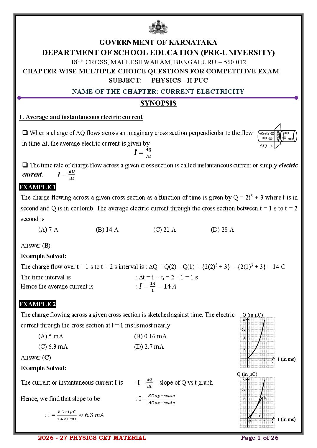
The charge flowing across a given cross section is sketched against time. The electric Q (in C)
16
current through the cross section at t = 1 ms is most nearly 12
(A) 5 mA (B) 0.16 mA 8
(C) 6.3 mA (D) 2.7 mA 4
Answer (C) 1 2 t (in ms)
3
Example Solved:
Q (in C)
𝑑𝑄 16
The current or instantaneous current I is : I = 𝑑𝑡 = slope of Q vs t graph
12
𝐵𝐶×𝑦−𝑠𝑐𝑎𝑙𝑒
Hence, we find that slope to be : I = 𝐴𝐶×𝑥−𝑠𝑐𝑎𝑙𝑒 8 B
4
8.5×1𝜇𝐶
: I = 1.4×1 𝑚𝑠 ≈ 6.3 𝑚𝐴 C
A 1 2 3 t (in ms)
2026 - 27 PHYSICS CET MATERIAL Page 1 of 26
Page 2
❑ The current density through a given conductor is the ratio of electric 𝑆⃗
current and the area of the cross section across which the current is 𝑛̂
𝑗⃗
passed.
𝑰
Hence 𝒋⃗ = 𝑺 𝒏
̂ Q →
❑ where 𝑛̂ is the unit vector in the direction of current density.
❑ Current density is a vector. Its SI unit is ampere-meter−2 (Am-2)
❑ The electric current can be expressed in terms of current density 𝑗⃗as
𝑰 = 𝒋⃗ • ⃗𝑺⃗ = 𝒋𝑺𝒄𝒐𝒔𝜽
where is the angle between 𝑗⃗ and 𝑆⃗.
EXAMPLE 3
2
If the charge flow through a conductor having circular cross section of radius mm is varying with time
√𝜋
according to Q = 3t2 (where t is in ms and Q is in C), the current density through the cross section at t = 1 s
is
(A) 1500 A/m2 (B) 150 A/m2 (C) (1500/) A/m2 (D) 1.5 A/m2
Answer (A)
Example Solved:
𝑑𝑄 𝑑
The instantaneous current through the cross section is : 𝐼 = 𝑑𝑡 = 𝑑𝑡 (3𝑡 2 ) = 6𝑡
At t = 1 s, the current is : I = 6(1) = 6 mA = 6 10-3 A
2 2
The area of the cross section is : S = r2 = ( 𝜋 × 10−3 ) = 4 10−6 m2
√
𝑰 𝟔×𝟏𝟎−𝟑
Hence the current density is : 𝒋 = 𝑺 = 𝟒×𝟏𝟎−𝟔 = 𝟏𝟓𝟎𝟎𝑨/𝒎𝟐
EXAMPLE 4
The current density through a region is 𝐽⃗ = (200 𝐴)(𝑖̂ + 𝑗̂) in /m2. The electric current through a surface,
parallel to x – z plane with magnitude of 1 mm2 is
(A) 0.2 A (B) 0.2 kA (C) 0.2 mA (D) 200 mA
Answer (D)
Example Solved:
The area vector of the surface is likely : 𝑆⃗ = (1 mm2) 𝑗̂ = (10−6 m2) 𝑗̂
Since the electric current is given by : 𝐼 = 𝐽⃗ • 𝑆⃗,
we have : 𝐼 = (200𝑖̂ + 200𝑗̂ + 0𝑘̂) • (0𝑖̂ + 10−6 𝑗̂ + 0𝑘̂)
or : I = 0.2 mA.
2026 - 27 PHYSICS CET MATERIAL Page 2 of 26
Page 3
❑ If I is the steady current through a conductor, n is the number charge density of the charge carriers in it, e
is the fundamental charge, A is the area of cross section of the conductor and if vd is the drift velocity of the
charge carriers, then 𝑰 = 𝒏𝒆𝑨𝒗𝒅
❑ In terms of current density, 𝒋⃗ = −𝒏𝒆𝒗
⃗⃗𝒅
EXAMPLE 5
Two conductors L and M have number charge densities in the ratio of 1:1.2 and areas of cross section in the
ratio of 3:4. To maintain the same steady currents through them, the drift velocities in them must be in the
ratio of
(A) 1 : 4.8 (B) 1 : 1.6 (C) 1.32:1 (D) 1.6:1
Answer (D)
Example Solved:
𝐼
The required expression here is : I = neAvd → 𝑣𝑑 = 𝑛𝑒𝐴
1
To keep I constant, ( e is constant anyway) : 𝑣𝑑 ∝ 𝑛𝐴,
𝑣 𝑛 𝐴
we have : 𝑣 𝑑,𝐿 = 𝑛𝑀 × 𝐴𝑀
𝑑,𝑀 𝐿 𝐿
𝑣𝑑,𝐿 1.2 4 1.6
Or : = × = 1.6 =
𝑣𝑑,𝑀 1 3 1
EXAMPLE 6
The following diagram represents the variation of the current density through a j (in 106 Am-2 )
16
conductor with drift velocity of the charge carriers. The product of charge carrier
12
density of the conductor and fundamental charge is
8
(A) 6 × 10³ 𝐶/𝑚3 (B) 6 × 10³ 𝐶𝑚−3 4
1 2 3
(C) 6 × 10⁹ 𝐶𝑚3 (D) 6 × 10⁹ 𝐶𝑚−3 vd (in mm/s)
→
Answer (C)
Example Solved:
According to the relation : j = nevd,
we find : j = (ne) vd
Comparing this with : y = mx,
we see that : slope m = ne = product of charge carr., density and fund., charge
(14−2)×106
Hence : ne = (3−1)×10−3 = 6 × 10⁹ 𝐶𝑚−3
2026 - 27 PHYSICS CET MATERIAL Page 3 of 26
Page 4
❑ If 𝑗⃗is the current density through a conductor, 𝐸⃗⃗ is the electric field inside the conductor, then
𝒏𝒆𝟐 𝝉
𝒋⃗ = ( ) ⃗𝑬⃗
𝒎
where n is the number charge density of charge carriers, e is the fundamental charge, m is the electronic
mass and is the relaxation time.
𝑛𝑒 2 𝜏
❑ The quantity is also called conductivity of the material of the conductor.
𝑚
𝒏𝒆𝟐 𝝉
Thus conductivity 𝝈 = .
𝒎
❑ The reciprocal of conductivity is resistivity.
𝟏 𝒎
Hence resistivity 𝝆 = 𝝈 = 𝒏𝒆𝟐 𝝉
EXAMPLE 7
The resistivity of the material of the conductor A is 102 times greater than the resistivity of the material of
𝐸
conductor B. The ratio of the electric field to current density ( 𝑗 ) in A to that in B is
(A) 0.1 (B) 0.01 (C) 1 (D) 100
Answer (D)
Example Solved:
1
The required expression for future manipulation is :𝑗 = 𝜌×𝐸
𝐸
Or :𝜌= 𝑗
(𝐸/𝑗) 𝜌 102 𝜌𝐵
Hence the required ratio is : (𝐸/𝑗)𝐴 = 𝜌𝐴 = = 100
𝐵 𝐵 𝜌𝐵
EXAMPLE 8
The graph that correctly depicts the variation of conductivity of the material of the conductor and the
relaxation time of the charge carriers shown below is
(A) (B) (C) (D)
Answer (C)
Example Solved:
𝑛𝑒 2 𝜏
The required expression is :𝜎= 𝑚
𝑛𝑒 2
Or we may write :𝜎 =( 𝑚 )×𝜏
This variation is similar to : y = mx → STRAIGHT LINE.
2026 - 27 PHYSICS CET MATERIAL Page 4 of 26
Page 5
❑ In the case of conductors, the mobility of the charge carriers is the ratio of their drift velocity and the
electric field.
|𝑣
⃗⃗ |
That is 𝜇 = |𝐸⃗⃗𝑑|
𝟐
𝒏𝒆 𝝉
From 𝒋⃗ = [ 𝒎 ]𝑬⃗⃗⃗
𝑛̸ 𝑒 2̸ 𝜏
we find 𝑛̸ 𝑒̸ 𝑣⃗𝑑 = [ 𝑚 ]𝐸⃗⃗
|𝑣
⃗⃗𝑑 | 𝑒𝜏
Or ⃗
⃗
|𝐸 |
= =𝜇
𝑚
EXAMPLE 9
Mobility of the charge carriers increases if
(A) their drift velocity is increased. (B) electric field inside the conductor is decreased.
(C) the mass of the charge carrier is increased. (D) their relaxation time is increased.
Answer (D)
Example Solved:
|𝑣
⃗⃗ | 𝑒𝜏
From the expression : 𝑚𝑜𝑏𝑖𝑙𝑖𝑡𝑦𝜇 = |𝐸⃗⃗𝑑| = 𝑚
we find : Choice (1) as vd is increased, E will also increase keeping fixed.
: Choice (2) as E is decreased, vd will also decrease keeping fixed.
: Choice (3) as m is increased, will decrease.
: Choice (4) as is increased, will increase.✓
6. Macroscopic form of Ohm’s law:
❑ If V is the potential difference across the ends of a conductor, I is the steady current through it, according
to Ohm’s law
𝑽 = 𝑰𝑹
where R is called the resistance of the conductor.
❑ The above expression is valid if (i) temperature remains constant (ii) other physical conditions such
as pressure and density of the surroundings is constant.
❑ If l is the length of the conductor, A is its area of cross section, the resistance of that conductor is given
𝒍
by 𝑹 = 𝝆𝑨 .
where is the resistivity of the material of the conductor.
2026 - 27 PHYSICS CET MATERIAL Page 5 of 26
Page 6
The variation of current through a wire is drawn against the potential difference across 10
I (in A )
area of cross sec tion
its ends. If the ratio of lengh of the conductor is 1.5 10-6 m, the resistivity of the material 8
(in micro ohm . meter) of the wire is 4
2
(A) 1.5 (B) 2.25 (C) 4.5 (D) 1
4 8 12
V (in volt)
Answer (B) →
Example Solved:
𝑉 1 1
The resistance of the wire is : 𝑅 = 𝐼 = 𝑠𝑙𝑜𝑝𝑒 = 8−0 = 1.5𝛺
12−0
𝑙 𝐴
From the expression : 𝑅 = 𝜌𝐴 𝜌 = 𝑅 𝑙
Hence : 𝜌 = (1.5)(1.5 × 10⁻⁶ ) = 2.25 × 10⁻⁶ 𝛺𝑚
7. Variation of resistivity and resistance with temperature:
❑ If resistivity of the material of a conductor changes by d for a change of temperature dT and if is the
resistivity of the material of the wire at a particular temperature T, then
𝑑𝜌 = 𝜌𝛼𝑑𝑇
where = temperature coefficient of resistivity of the material of the conductor.
𝟏 𝒅𝝆
Thus we may write 𝜶 = 𝝆 𝒅𝑻
❑ For conductors, over a wide range of temperature, the variation of the
→
resistivity with temperature is given by
𝝆 = 𝝆𝟎 𝒆𝜶(𝑻−𝑻𝟎 )
where 0 is the resistivity at temperature T0.
T (in K) →
❑ The graphical variation of with T can be represented as shown to the right.
❑ If the temperature difference T – T0 is not large, i.e., (T – T0) < < 1, then we may write
= 0[ 1 + (T – T0)]
→
Expanding it, we obtain = [0 (1 − T0)] + (0)T
0 (1 - T0) Slope = 0
Since 0 , and T0 are constants, the quantity
T (in K)
0 (1 − T0) = constant C (say,) →
while 0 = m is another constant.
Hence the above expression resembles y = C + mx. This is an equation for the straight line as shown.
2026 - 27 PHYSICS CET MATERIAL Page 6 of 26
Page 7
write R = R0[ 1 + (T – T0)]
provided, dimensions of the conductor do not appreciably change.
❑ If R1 is the resistance of a conductor at temperature T1 and R2 is its resistance at temperature T2, then the
temperature coefficient of resistance can be written as
𝑹 −𝑹
𝜶 = 𝑹 𝑻𝟐 −𝑹𝟏 𝑻
𝟏 𝟐 𝟐 𝟏
❑ In the event, the temperature change also brings about the change in the dimensions of the conductor, the
fractional change in the resistance when the temperature changes by dT is
𝒅𝑹
= (𝜶 − 𝜷)𝒅𝑻
𝑹
Where is the linear expansion coefficient and is the temperature coefficient of resistance.
EXAMPLE 11
The resistance of a conductor at temperature T1 is R1. Its resistance at temperature T2 is R2. If T2 > T1, for a
conductor, it is necessary that
(A) R1T2 < R2T1 (B) R1T2 > R2T1 (C) R1T2 = R2T1 (D) R1T1 > R2T2
Answer (B)
Example Solved:
𝑅 −𝑅
From the expression : 𝛼 = 𝑅 𝑇2−𝑅1𝑇 ,
1 2 2 1
since for a conductor :>0
and given that : T2 > T1 so that R2 > R1,
we find that the denominator expn : R1T2 – R2T1 > 0 → R1T2 > R2T1
8. Resistor Combinations
(a) Series combination
❑ When n resistors R1, R2, R3,……., Rn are connected in series, the
effective resistance is given by R1 R2 R3 Rn
𝑹𝑺 = 𝑹𝟏 + 𝑹𝟐 +. . . . . . . . . . . . . +𝑹𝒏
❑ When only two resistors R1 and R2 are connected in series, R1 R2
𝑹𝑺 = 𝑹𝟏 + 𝑹𝟐
❑ When n resistors all having R are connected in series, the effective resistance is
𝑹𝑺 = 𝒏𝑹
R R R R
2026 - 27 PHYSICS CET MATERIAL Page 7 of 26
Page 8
difference across the combination is given by
𝟏 𝑹
𝑽𝟏 = 𝑹 +𝑹 ×𝑽 V1 V2
𝟏 𝟐
𝑹 R1 R2
𝟐
Similarly, the p.d across R2 is given by 𝑽𝟐 = 𝑹 +𝑹 ×𝑽 V
𝟏 𝟐
(b) Parallel combination R1
❑ When n resistors R1, R2, R3,……., Rn are connected in parallel, the effective resistance R2
is given by
𝟏 𝟏 𝟏 𝟏 Rn
= 𝑹 + 𝑹 +. . . . . . . . . . . . . + 𝑹
𝑹𝑷 𝟏 𝟐 𝒏
❑ When only two resistors R1 and R2 are connected in parallel,
𝑹 𝑹
𝑹𝑷 = 𝑹 𝟏+𝑹𝟐
𝟏 𝟐
R1
❑ When n resistors all having R are connected in parallel, the effective resistance is
𝑹
𝑹𝑷 = 𝒏
R2
❑ When two resistors are connected in parallel, the current through R1 in terms of total current through
the combination is given by
𝑹 ×𝑰
I1 R1
𝑰𝟏 = 𝑹 𝟐+𝑹
𝟏 𝟐
I
𝑹𝟏 ×𝑰
Similarly, the current through R2 is given by 𝑰𝟐 = 𝑹 +𝑹 I2 R2
𝟏 𝟐
EXAMPLE 12
A wire of length L is connected across a battery. It draws a current I. It is then cut into n identical pieces.
These pieces are connected in parallel across the same battery. The total current drawn by the combination is
(A) I/n2 (B) n2I (C) nI (D) I/n
Answer (B)
Example Solved:
𝑉
Let each piece have resistance R, then initial current is : I = 𝑛𝑅
𝑅
When it is cut into n pieces and connected in parallel : total resistance R =
𝑛
𝑉 𝑉 𝑛𝑉
Hence the new current is : I = 𝑅′ = 𝑅 = 𝑅
( )
𝑛
𝑉
After some simplification : I = 𝑛2 × 𝑛𝑅 = 𝑛2 𝐼
EXAMPLE 13
The effective resistance (of the circuit shown) across a and b is 30 30
(A) (124/13) (B) 3 a b
60
(C) 19 (D) 5 45 15
Answer (B)
2026 - 27 PHYSICS CET MATERIAL Page 8 of 26
Page 9
The highlighted resistors : 30 and 30 are in series. 30 30
60
a b
Hence effective resistance of them : 𝑅1 = 30 + 30 = 60𝛺
45 15
Now, the highlighted resistors : 45 and 15 are in series.
Hence their effective resistance is : 𝑅2 = 45 + 15 = 60𝛺 60
60
a b
Now, the highlighted resistors : 60 and 60 are in parallel.
45 15
60
Hence their effective resistance is : 𝑅3 = 2 = 30𝛺
60
Finally, the two highlighted : 60 and 30 are in series. 60
a b
Hence the effective resistance across
60
a and b : 𝑅𝑎𝑏 = 60 + 30 = 90𝛺
9. Electric Power:
❑ If V is the potential difference between the ends of a resistor having resistance R and I is the steady
current through it, the power delivered to the resistor by the battery is 𝑃 = 𝐼𝑉 .
❑ The power dissipated across the resistor is given by
𝑽𝟐
𝑷 = 𝑹 = 𝑰𝟐 𝑹
❑ If Prated is the rated power and Vrated is the rated voltage (potential difference) of a bulb, then the
𝑽𝟐
resistance of the bulb is 𝑹 = 𝑷𝒓𝒂𝒕𝒆𝒅 .
𝒓𝒂𝒕𝒆𝒅
EXAMPLE 14
An electric bulb rated at 40 W, 200 V is connected in series with another bulb rated 60 W and 220 V. If the
combination is now connected across a 220 V power supply the current drawn by the combination is
(A) 120 A (B) 12 A (C) 1.2 A (D) 0.12 A
Answer (D)
Example Solved:
2002 2202
The resistances of bulb 1 and bulb 2 are respectively : 𝑅1 = 40 = 1000𝛺 and 𝑅2 = 60 = 807𝛺.
𝑉 220
Hence the total current drawn by the combination is : 𝐼 = 𝑅 +𝑅 = 1000+807 = 0.12 𝐴.
1 2
11. Emf and Internal Resistance:
❑ If E is the emf of a cell, r is its internal resistance, R is the external resistor and
I is the total current through the circuit, r
E
❑ the terminal potential difference is given by 𝑽 = 𝑬 − 𝑰𝒓 I V
𝑬
❑ The total current through the circuit is 𝑰 = 𝑹+𝒓 .
❑ Hence the terminal pd is given by 𝑽 = 𝑰𝑹 =
𝑬𝑹
. R
𝑹+𝒓
2026 - 27 PHYSICS CET MATERIAL Page 9 of 26
Page 10
If E is the emf of a cell, r is its internal resistance, R is the external resistance across it, then the power
dissipated across the external resistor is
𝐸2 𝑅 𝐸2 𝑅2 𝐸 2 √𝑅 𝐸𝑅
(A) (𝑅+𝑟)2 (B) (𝑅+𝑟)3 (C) (𝑅+𝑟)3/2 (D) (𝑅+𝑟)2
Answer (A)
Example Solved:
𝐸
The current through the external resistor is : 𝐼 = 𝑅+𝑟
Since the power dissipated across the external resistor is : P = I2R,
𝐸2𝑅
we get :P=
(𝑅+𝑟)2
11. Combinations of cells:
(a) Cells in series:
❑ If E1, E 2, ……, E n are the emfs of cells connected in series, r1, r2,……., rn are their respective internal
resistances, then the effective emf of the combination is given by
𝑬𝑺 = 𝑬𝟏 + 𝑬𝟐 +. . . . . . . . . . . . . +𝑬𝒏
E1 r1 E2 r2 En rn
❑ and the effective internal resistance of the combination is I R
𝒓𝑺 = 𝒓𝟏 + 𝒓𝟐 +. . . . . . . . . . . . . +𝒓𝒏
(b) Cells in parallel:
❑ If E 1, E 2, ……, E n are the emfs of cells connected in parallel, r1, r2,……., rn are
E1 r1
their respective internal resistances, then the effective emf of the combination is given by
𝑬𝑷 𝑬 𝑬 𝑬 E2 r2
= 𝒓 𝟏 + 𝒓 𝟐 +. . . . . . + 𝒓 𝒏
𝒓𝑷 𝟏 𝟐 𝒏
❑ where the effective internal resistance of the combination is given by En rn
I
𝟏 𝟏 𝟏 𝟏
= 𝒓 + 𝒓 +. . . . . . + 𝒓 R
𝒓𝑷 𝟏 𝟐 𝒏
❑ If only two cells of emfs E1 and E2 of internal resistances r1 and r2 are respectively are in parallel
combination across an external resistor R, the effective emf and effective internal resistance are
𝑬𝟏 𝒓𝟐 +𝑬𝟐 𝒓𝟏 𝒓 𝒓
𝑬𝑷 = and 𝒓𝑷 = 𝒓 𝟐+𝒓𝟏 respectively.
𝒓𝟏 +𝒓𝟐 𝟏 𝟐
EXAMPLE 16
15 V, 2
The potential difference across the 16.8 resistor is
10 V, 3
(A) 4.2 V (B) 15.1 V (C) 8.4 V (D) 0
5 V, 2
Answer (C)
16.8
2026 - 27 PHYSICS CET MATERIAL Page 10 of 26
Page 11
We first see that : 15 V || 10 V 15 V, 2
5 V, 1.2
(15)(3)−(10)(2)
The effective emf of these two cells, : 𝐸1 = = 5V 10 V, 3
3+2
5 V, 2
(3)(2)
Internal resistance of this combination : 𝑟1 = 3+2 = 1.2 Ω 5 V, 2
16.8
16.8
Further it is seen that :5V5V
Hence the effective emf : E = 5 + 5 = 10 V
The total internal resistance is : r = 1.2 + 2 = 3.2
𝐸𝑅 10×16.8
Hence the pd across 16.8 resistor : V = 𝑅+𝑟 = 16.8+3.2 = 8.4𝑉
12. Kirchhoff’s rules:
❑ (i) Kirchhoff’s junction rule (KJR) : The algebraic sum of currents entering and leaving a junction in
an electrical network is always zero.
If I1, − I2, ….., In are the currents entering or leaving a junction of particular electrical network, according to
KJR,
∑ 𝑰𝒊 = 𝑰𝟏 ± 𝑰𝟐 +. . . . . . . . . . . . . ±𝑰𝒏 = 𝟎
I4
I2 R1 E1 I3 R3 E2 I2
Junction E3
R2
I1 I3 R6
R8 R4 E4 R5 R7
I1
Fig Fig
(1) (2)
❑ (ii) Kirchhoff’s loop rule (KLR) : The algebraic sum of potential differences across resistors and emfs
of cells in a closed loop of an electrical network is zero.
If E1, E 2, ….., E n are the emfs of the cells , I1R1, I2R2,…. are the pds across the resistors in a closed loop of
particular electrical network, according to KLR,
∑ 𝑽 = 𝑬𝟏 ± 𝑰𝟏 𝑹𝟏 + 𝑬𝟐 ± 𝑰𝟐 𝑹𝟐 +. . . . . . . . . . . . ± + 𝑬𝒏 ± 𝑰𝒏 𝑹𝒏 = 𝟎
EXAMPLE 17
In the figure, a current of 0.5 A passes through 19 resistor •B
towards the right. A current of 0.2 A passes through 10 V cell 10
along DC. The potential of point A and current through 10 5 V, 1
A• •
resistor are respectively 19
D 10 V, 2
(A) – 5.4 V and 0.3 A along BD
(B) + 5.4 V and 0.3 A along DB •C
(C) 10 V and 0.2 A along BD
(D) – 10 V and 0.3 A along DB
Answer (B)
2026 - 27 PHYSICS CET MATERIAL Page 11 of 26
Page 12
•B
The above circuit may be
10
5V
20
redrawn as shown :→ 0.5 A
• I
A• 10 V
2
VA D
0.2 A •C
Applying KLR to loop
ADCA, : +VA – 5 – (20 0 .5) + 10 – (2 0.2) = 0
Or : VA = 5.4 V.
Applying KJR to junction D, : I = 0.5 − I − 0.2 = 0 I = − 0.3 A.
Hence the current through DB is : from D to B.
13. Wheatstone Bridge:
•B
❑ If R1, R2, R3 and R4 are the resistances of the four branches of a Wheatstones R2 R4
bridge, when it is balanced, A• •C
G
(i) current through the galvanometer is zero → Ig = 0,
R1 RO
•
(ii) the potentials at B and D are identical
D
𝑅1 𝑅3 E
and (iii) 𝑅 = 𝑅 .
2 4
EXAMPLE 18 30
In the figure, the electric current I is 0.3 A. Then the current I1 is I 20 50
15 I1
(A) 0.1 A (B) 0.2 A (C) 0.25 A (D) 0.4 A
25
Answer (B)
Example Solved: 30
•B
50
Then the same circuit can be redrawn as shown : I
20
A• I1 •C
𝑅1 𝑅3
We first verify if :𝑅 =𝑅 15 25
2 4 •
D
15 25
Hence : = ✓
30 50
Since the network is : balanced,
the : 20 resistor is removed.
𝑅 +𝑅
Using the current divider rule, : 𝐼1 = 𝑅 +𝑅2+𝑅4+𝑅 × 𝐼
1 2 3 4
30+50
Hence : 𝐼1 = 15+30+25+50 × 0.3 = 0.2 ⥂ 𝐴
********
2026 - 27 PHYSICS CET MATERIAL Page 12 of 26
Page 13
1. The potential difference applied to an X-ray tube is 5 kV and the current through it is 3.2 mA. Then the
number of electrons striking the target per second is
(A) 2 1016 (B) 5 106 (C) 1 1017 (D) 4 1015
2. A beam of electrons moving at a speed of 106 m/s along a line produces a current of 1.6 10–6 A. The
number of electrons in the 1 metre of the beam is
(A) 106 (B) 107 (C) 1013 (D) 1018
3. According to Bohr’s model of hydrogen atom, the electron revolves around the nucleus in a circular orbit
of a radius 5.3 10–11 metre. Its frequency is 6.5 1015 Hz. The current associated is
(A) Zero (B) 1.05 10–6 A (C) 3.4 104 A (D) 1.05 10–3 A
4. A copper wire of length 1 m and radius 1 mm is joined in series with an iron wire of length 2 m and radius
3 mm and a current is passed through the wire. The ratio of current densities in the copper and iron wire
is
(A) 9 : 1 (B) 18 : 1 (C) 6 : 1 (D) 2 : 3
5. In a region 1019 alpha particles move to the right, 1019 protons move to the left, 1019 electrons move to the
left per second. The resultant current is
(A) 3.2 A towards left (B) 3.2 A towards right
(C) 6.4 A towards left (D) 6.4 A towards right
6. The I – V graphs for two different electrical appliances A and B are as shown in the adjacent diagram. If
RA and RB be the resistance of the devices then
(A) RA = RB
(B) RA > RB
(C) RA< RB
(D) Data insufficient
7. The I – V graph for a conductor makes an angle with the current I axis (along Y-axis). The resistance of
the conductor is given by
(A) sin (B) cos (C) tan (D) cot
8. A wire of length L and resistance R is stretched such that its diameter is reduced to half of its original
diameter. What is the new resistance of the wire?
(A) 4R (B) 5R (C) 8R (D) 16R
9. The lengths and cross-sectional areas of four copper wires A , B, C and D are respectively (l/2, 2A),
(2l, A/2), (2l, 2A) and (l/2, A/2). The wire which has the maximum resistance is
(A) A (B) B (C) C (D) D
2026 - 27 PHYSICS CET MATERIAL Page 13 of 26
Page 14
Column-I Column-II
and in column-II charge carriers are
listed. (i) Metals (a) positive and negative ions
Match the following. (ii) Electrolytic solution (b) positive ions and electrons
(A) i-a, ii-d, iii-b, iv-c
(iii) Gaseous conductors (c) free electrons and holes
(B) i-d, ii-a, iii-b, iv-c
(C) i-d, ii-a, iii-c, iv-b (iv) Semiconductors (d) free electrons
(D) i-a, ii-d, iii-c, iv-b
11. A potential difference of 3.0 V has been applied across a metal conductor of length 60 cm. If relaxation
time for electrons in that metal be 2.5 10–14 s , then the magnitude of drift velocity will be
(A) 2.2 10–2 m/s (B) 2.2 10–4 m/s (C) 1.1 10–3 m/s (D) 1.1 10–2 m/s
12. Two wires A and B of the same material, having radii in the ratio 1:2 and carry currents in the ratio 4:1.
The ratio of drift speeds of electrons in A and B is
(A) 16:1 (B) 4:1 (C) 1:16 (D) 1:4
13. If the current flowing through a copper wire of 1 mm diameter is 1.1A. The drift velocity of electron is
(Given density of copper is 9 g/cm3, atomic weight of copper is 63 gram and one free electron is
contributed by each atom)
(A) 0.1 mm/s (B) 0.2 mm/s (C) 0.3 mm/s (D) 0.4 mm/s
14. A copper wire of length 2 m and cross-sectional area 0.1 cm2 has 8 1028 free electrons/m3. If the wire
carries a current of 2.5 A, the drift speed of the electron is
(A) 2.0 10–3 m/s (B) 2 10–4 m/s (C) 2 10–5 m/s (D) 0.2 m/s
15. Which of the following characteristics of electrons determines the current in a conductor?
(A) Drift velocity alone. (B) Thermal velocity alone.
(C) Both drift velocity and thermal velocity. (D) Neither drift nor thermal velocity.
16. A wire has a non-uniform cross-sectional area as shown in the figure. A steady current I flows through it.
Which one of the following statements is correct?
(A) The drift speed of electron is constant.
(B) The drift speed of electron increases while moving from A to B.
(C) The drift speed of electron decreases while moving from A to B.
(D) The drift speed of electron varies randomly.
17. Assertion: If the length of the conductor is doubled, the drift velocity will become half of the original value
(keeping potential difference unchanged).
Reason: At constant potential difference, drift velocity inversely proportional to the length of the
conductor.
(A) Both Assertion and Reason are true and the Reason is correct explanation of the Assertion.
(B) Both Assertion and Reason are true but Reason is not correct explanation of the Assertion.
(C) Assertion is true but Reason is false.
(D) Assertion is false but the Reason is true.
2026 - 27 PHYSICS CET MATERIAL Page 14 of 26
Page 15
(A) The drift speed acquired by free electrons per unit electric field is called mobility.
(B) The conductivity of semiconductors decreases with increase in temperature.
(C) The conductivity of conductors decreases with increase in temperature.
(D) Alloys are widely used in the construction of standard resistors.
19. The resistivity of manganin is 50 10–8 m. The resistance of a manganin cube having length 50 cm is
(A) 10–6 (B) 2.5 10–5 (C) 10–8 (D) 5 10–4
20. An aluminium rod of length m has cross-sectional area 2 mm2. What should be the radius of another
rod of 1 m length of same material to have equal resistance?
(A) 1 mm (B) 2 mm (C) 4 mm (D) 6 mm
21. The length of a hollow tube is 3.14 m, its outer diameter is 10 cm and thickness of its wall is 10 mm. If
resistivity of the material of the tube is 9 10–4 m then resistance of tube will be
(A) 1 (B) 2 (C) 3.14 (D) 9/19
22. Two conductors are made of the same material and have same length. Conductor A is a solid wire of
diameter 1 mm. Conductor B is a hollow tube of outer diameter 2 mm and inner diameter 1 mm. What is
the ratio of resistances RA to RB?
(A) 1 : 3 (B) 3 : 1 (C) 2 : 3 (D) 3 : 2
23. If a copper wire is stretched to make it 0.1% longer, the percentage increase in resistance will be
(A) 0.1% (B) 0.2% (C) 0.4% (D) 1%
24. Dimensions of a conductor are 1 cm 1 cm 1 m. If the resistivity of its material is 3 10–7 m, then
the resistance between its opposite square faces is
(A) 3 10–7 (B) 3 10–5 (C) 3 10–3 (D) 3 10–2
25. Two wires are made up of two different materials whose resistivities are in the ratio 2:3, lengths in the
ratio 3:4 and radii in the ratio 4:5. The ratio of their resistances is
(A) 3 : 4 (B) 6 : 5 (C) 2 : 5 (D) 25 : 32
26. Masses of three wires made up same material are in the ratio 1:3:5 and their lengths are in the ratio 5:3:1.
The ratio of their electrical resistance is
(A) 1:3:5 (B) 5:3:1 (C) 125 : 15 : 1 (D) 1:15:125
27. An electric current of 2A is passed through a circuit containing three wires arranged in parallel. If the
length and radii are in the ratio 2:3:4 and 3:4:5, then the ratio of currents passing through the wires is
(A) 3:6:10 (B) 4:9:16 (C) 9:16:25 (D) 54:64:75
28. A conductor carries a current of 50 A. If the area of cross section of the conductor is 50 mm2 then the
current density in the wire is
(A) 0.5 Am–2 (B) 1 Am–2 (C)10–3 Am–2 (D) 10–6 Am–2
29. When an electric field of 510–3 NC–1 is applied to a conductor, a current density of 2.5 105 Am–2 is
found to exist. The resistivity of conductor is
(A) 1.0 10–8 m (B) 2.0 10–8 m (C) 0.5 108 m (D) 12.5 102 m
2026 - 27 PHYSICS CET MATERIAL Page 15 of 26
Page 16
a speed of 105 m/s. The current density is
(A) 6.4 A/m2 (B) 3.2 A/m2 (C) 1.6 A/m2 (D) 32 A/m2
31. The dimensional formula for resistivity is [] = [M1 Lx T–3 A–y]. The values of x and y are respectively
(A) 2, – 3 (B) 3, –2 (C) 3, 2 (D) –2, 3
32. A uniform copper wire of length 1 m and cross-sectional area 0.5 mm2 carries a current of 1 A. Assuming
that there are 8 1028 free electrons per m3 in copper, how long will an electron take to drift from one
end of the wire to the other?
(A) 6.4102 s (B) 8.0103 s (C) 3.2 103 s (D) 6.4103 s
33. A copper wire (resistivity = 1.7 10–8 m) of length 50 cm and area of cross section 1 mm2 carries a
current of 0.5 A. The electric field across the wire is
(A) 8.5 V/m (B) 0.85 V/m (C) 0.085 V/m (D) 0.0085 V/m
34. Match the following Column-I with Column-II. Column-I Column-II
(A) i-a, ii-d, iii-b, iv-c (i) Electrical resistance (a) [M L3 T–3 A–2]
(B) i-d, ii-a, iii-b, iv-c (ii) Electrical resistivity (b) [M–1 T2 A]
(C) i-d, ii-a, iii-c, iv-b (iii) Mobility (c) [M L2 T–3 A–1 ]
(D) i-a, ii-d, iii-c, iv-b
(iv) Electromotive force (d) [M L2 T–3 A–2]
35. Statement-I: The resistivity of metals increases with increase in temperature.
Statement-II: Increasing the temperature of metals causes more frequent collisions of electrons.
(A) both the statements I and II are true and II is the correct explanation of I.
(B) both statements I and II are true but II is not the correct explanation of I.
(C) Statement-I is true but II is false.
(D) both statements-I and II are false.
36. In copper, the number density of free electrons is 8 1028 m–3 and its resistivity is 1.710–8 Ω m.
What is the relaxation time of free electrons in copper?
Take the mass of electron = 9 10–31 kg and e = 1.6 10–19 C.
(A) 4.2 10–15 s (B) 4 1013 s (C) 2.6 1014 s (D) 2.6 10–14 s
37. The resistance of a coil is 4.2 at 100C and the temperature coefficient of resistivity of its material is
0.004/C. Then its resistance at 0C is
(A) 3 (B) 3.5 (C) 4 (D) 5
38. A wire has a resistance 10 . It is stretched by one-tenth of its original length. Then its resistance becomes
(A) 9 (B) 10 (C) 11 (D) 12.1
39. Nichrome wire is used in making standard resistance because its
(A) resistivity is low
(B) melting point is high
(C) density is high
(D) temperature coefficient of resistance is negligible.
2026 - 27 PHYSICS CET MATERIAL Page 16 of 26
Page 17
resistance at 0C is
(A) 25C (B) 40C (C) 50 C (D) 60C
41. A piece of Aluminium (Al) and a piece of Germanium (Ge) are cooled from 300K to 250K. The resistance
(A) of both increases (B) of both decreases
(C) Al increase and Ge decrease (D) Al decrease and Ge increase
42. A silver wire has a resistance of 2.2 Ω at 25 °C, and a resistance of 2.8 Ω at 100 °C. The temperature
coefficient of resistivity of silver is
(A) 4 10–3 /C (B) 4 10–4 /C (C) 4 10–5 /C (D) 5 10–2 /C
43. Temperature dependence of resistivity ρ(T) of semiconductors, insulators and metals is significantly based
on which of the following factors?
(a) number of charge carriers can change with temperature T.
(b) time interval between two successive collisions can depend on T.
(c) length of material can be a function of T.
(d) mass of carriers is a function of T.
(A) both (a) and (b) (B) both (c) and (d)
(C) both (b) and (c) (D) all (a), (b), (c) and (d)
44. In the circuit shown, when the switch S is closed,
then the value of current i will be
(A) 2A (B) 3A
(C) 4A (D) 5A
45. Choose the correct alternative among the following:
(A) Alloys of metals usually have lesser resistivity than that of their constituent metals.
(B) Alloys usually have much higher temperature coefficients of resistance than pure metals.
(C) The resistivity of the alloy manganin is nearly independent of temperature.
(D) The resistivity of an insulator is greater than that of a metal by a factor of the order of 103.
46. From the graph between current i and voltage V shown, identity the portion
corresponding to negative resistance.
(A) DE (B) CD
(C) BC (D) AB
47. The circuit in figure shows two cells connected in
opposition to each other. Cell 𝐸1 is of emf 6V and
internal resistance 2 Ω; the cell 𝐸2 is of emf 4V and
internal resistance 8Ω. The potential difference
between the points A and B is
(A) 3.6 V (B) 5.6 V
(C) 2 V (D) 1.6 V
2026 - 27 PHYSICS CET MATERIAL Page 17 of 26
Page 18
resistances 𝑟1 and 𝑟2 respectively are connected in parallel as
shown in figure.
(A) The equivalent emf 𝜀𝑒𝑞 of the two cells is between 𝜀1
and 𝜀2 , i.e. 𝜀1 < 𝜀𝑒𝑞 < 𝜀2.
(B) The equivalent emf 𝜀𝑒𝑞 is smaller than 𝜀1
(C) The 𝜀𝑒𝑞 is given by 𝜀𝑒𝑞 = 𝜀1 + 𝜀2 always.
(D) 𝜀𝑒𝑞 is independent of internal resistances 𝑟1 and 𝑟2 .
49. A 10V battery with internal resistance 1 Ω and a 15V battery with internal resistance
0.6 Ω are connected in parallel to a voltmeter (see figure). The reading in the
voltmeter will be close to :
(A) 11.9 V (B) 12.5 V
(C) 13.1 V (D) 24.5 V
50. A battery consists of variable number (n) of identical cells, each having an internal resistance r connected
in series. The terminals of the battery are short-circuited. A graph of current (I) in the circuit versus the
number of cells will be as shown in the figure
(A) (B) (C) (D)
51. A storage battery of emf 8.0 V and internal resistance 0.5 Ω is being charged by a 120 V dc supply using
a series resistor of 15.5 Ω. What is the terminal voltage of the battery during charging?
(A) 11.5V (B) 7.5V (C) 15 V (D) zero
52. For a cell terminal potential difference is 2.2V when the circuit is open and reduces to 1.8V when cell is
connected to a resistance of 𝑅 = 5 Ω. The internal resistance of the cell is
10 9 11 5
(A) 9 Ω (B) 10 Ω (C) 9 Ω (D) 9 Ω
53. A resistance R whose value is varied from 1 Ω to 5 Ω is connected to a cell of internal resistance 3 Ω. The
power consumed by R
(A) increases continuously (B) decreases continuously
(C) first decreases then increases (D) first increases then decreases
54. A circuit consists of three identical lamps connected to a battery as shown in the figure. When the switch
S is closed, the intensities of the lamps A and B
(A) will increase by eight times (B) will decrease by two times
(C) will increase by more than two times (D) will remain the same
2026 - 27 PHYSICS CET MATERIAL Page 18 of 26
Page 19
the current, the temperature of the wire is raised by ∆𝑇 in a time t. A number N of similar cells are now
connected in series with a wire of the same material and cross-section but of length 2L. The temperature
is raised by the same amount ∆𝑇 in the same time. The value of N is
(A) 4 (B) 6 (C) 8 (D) 9
56. In Figure, the ideal batteries have emfs 𝜀1 = 150𝑉 and 𝜀2 = 50𝑉 and the resistances are 𝑅1 = 3Ω and
𝑅2 = 2Ω. If the potential at P is 100 V, potential at Q will be
(A) 10 V (B) −10 𝑉 (C) 200 V (D) 50 V
57. The value of current in the 6 Ω resistance is
(A 8 A (B) 10 A (C) 4 A (D) 6 A
58. An immersion heater must increase the temperature of 1.50 kg of water from 10.0°C to 50.0°C in 10.0
min while operating at 100V. If the specific heat of water is 4200 SI units, the required resistance of the
heater is:
(A) 20Ω (B) 50Ω (C) 100Ω (D) 24Ω
59. Ideal gas is contained in a thermally insulated and rigid container and it is heated through a resistance of
100 Ω by passing a current of 1 A. Change in internal energy of the gas after 5 min will be
(A) zero (B) 10 kJ (C) 20 kJ (D) 30 kJ
60. Two electric bulbs rated at 25 W, 220 V and 100 W, 220 V are connected in series across a 220-V voltage
source. The 25-W and 100-W bulbs now draw 𝑃1 and 𝑃2 powers respectively. Then
(A) 𝑃1 = 16 𝑊 , 𝑃2 = 8 𝑊 (B) 𝑃1 = 4 𝑊 , 𝑃2 = 16𝑊
(C) 𝑃1 = 8 𝑊 , 𝑃2 = 4 𝑊 (D) 𝑃1 = 16 𝑊 , 𝑃2 = 4 𝑊
61. An electric bulb rated for 500 watts at 100 volts is used in a circuit having a 200-volt supply. The resistance
R that must be put in series with the bulb, so that the bulb draws 500 watts is ..
(A) 10 (B) 20 (C) 50 (D) 100
62. n identical cells, each of emf E and internal resistance r, are joined in series to form a closed circuit. The
potential difference across any one cell is
𝐸 𝑛−1
(A) zero (B) 𝐸 (C) (D) 𝐸
𝑛 𝑛
2026 - 27 PHYSICS CET MATERIAL Page 19 of 26
Page 20
insulated cylinder fitted with a frictionless piston of mass 𝑚 = 12 𝑘𝑔 and
containing an ideal gas. A current 𝑖 = 200 𝑚𝐴 flows through the coil, which has a
resistance 𝑅 = 600 Ω. Temperature of the gas remains unchanged if the piston
moves up with a speed
(A) 0.2 𝑚/𝑠 (B) 0.4 𝑚/𝑠
(C) 1 𝑚/𝑠 (D) 1.5 𝑚/𝑠
64. A circuit consists of three identical lamps connected to a battery as in the
figure. The battery has some internal resistance. The switch S, originally open,
is closed. The brightness of lamp B
(A) increases (B) decreases
(C) does not change (D) drops to zero
65. In the given circuit, each battery is 5 V and has an internal
resistance of 0.2 Ω. The reading in the ideal voltmeter V is
(A) 5 V (B) 40 V
(C) 30 V (D) zero
66. The value of current I in the circuit is
(A) 1 A (B) 3 A (C) 6 A (D) 2 A
67. The potential difference (𝑉𝐴 − 𝑉𝐵 ) between the points A and B in the given figure is
(A) –3 V (B) +3 V (C) +6 V (D) +9 V
68. The Figure given below shows current in a part of electric circuit. The current I is ____.
(A) 1.3 A (B) 1.7 A (C) 3.7 A (D) 1A
69. The below diagrams show four different ways in which currents 𝐼1 , 𝐼2 𝑎𝑛𝑑 𝐼3 can combine at a junction.
For which of these junctions is the equation 𝐼1 + 𝐼2 + 𝐼3 = 𝐼4 is correct?
2026 - 27 PHYSICS CET MATERIAL Page 20 of 26
Page 21
(A) Charge Accumulated at Node is Zero (B) Positive Charge Accumulated at Node
(C) No Charge Accumulated at Node (D)Energy Stored at Node
71. Which of the following law is used with Kirchhoff’s Current Law?
(A) Ohms law (B) Faraday’s law (C) Coulomb’s law (D) Both A and C
72. KVR is performed using___?
(A) Nodal analysis (B) Mesh analysis (C) Both a and b (D) voltage analysis
73. KCL is performed using___?
(A) Nodal analysis (B) Mesh analysis (C) Both a and b (D) current analysis
74. If a resistor(R) is traversed in the direction of current(I ), the potential change is ______.
(A) +IR (B) −IR (C) Zero (D)+E
75. A battery of emf 𝜀 is crossed from negative to positive terminal. The potential change is:
(A) −𝜀 (B) 𝜀 (C) Zero (D) ±𝐼𝑅
76. In a balanced Wheatstone bridge, the potential difference across the galvanometer is:
(A) Maximum (B) Equal to source voltage
(C) Zero (D) Infinite
77. Statement 1: Kirchhoff's rules are applicable only in DC circuits.
Statement 2: Kirchhoff's rules can also be applied to AC circuits using phasor analysis.
Select the correct option:
(A) Both Statement I and Statement II are true.
(B) Both Statement I and Statement II are false.
(C) Statement I is true but Statement II is false.
(D) Statement I is false but Statement II is true.
78. Match the column-1 with column-2
Column - 1 Column-2
(i) Kirchhoff’s current rule (a) law of conservation of energy
(ii) Kirchhoff’s voltage rule (b) conductor
(iii) Ohmic device (c) insulator
(iv) Non- Ohmic device (d) law of conservation of charge
(A) (i)- (d) , (ii)- (a), (iii)-(c),(iv)- (b) (B) (i)- (d) , (ii)- (a), (iii)-(b),(iv)- (c)
(C) (i)- (d) , (ii)- (b), (iii)-(c),(iv)- (a) (D) (i)- (a) , (ii)- (d), (iii)-(b),(iv)- (c)
79. Find the false statement.
(A) Sum of voltage over any closed loop is zero
(B) Kirchhoff’s Laws can be applied to any circuit, regardless of its structure and composition
(C) Kirchhoff’s 2nd law is applied at nodes
(D) Kirchhoff’s 1st law can be applied for both planar and non-planar circuits
80. Which of the following statements is correct?
(A) Kirchhoff’s law states that the current traveling towards a junction equals the voltage drop.
(B) The current flowing towards a junction is equal to the resistance across the junction, according to
Kirchhoff’s law.
(C) The current flowing into a junction is equal to the current exiting the junction, according to
Kirchhoff’s law.
(D) Kirchhoff’s law states that the current traveling towards a junction is equal to the sum of all currents
in the circuit.
2026 - 27 PHYSICS CET MATERIAL Page 21 of 26
Page 22
Column - 1 Column-2
(i) Junction Rule (a) ΣV = 0
(ii) Loop Rule (b) ΣI = 0
(iii) Conservation of charge (c) Kirchhoff’s Current Rule
(iv) Conservation of energy (d) Kirchhoff’s Voltage Rule
(A) (i)- (d) , (ii)- (c), (iii)-(a),(iv)- (b) (B) (i)- (c) , (ii)- (d), (iii)-(a),(iv)- (b)
(C) (i)- (b) , (ii)- (a), (iii)-(d),(iv)- (c) (D) (i)- (b) , (ii)- (a), (iii)-(c),(iv)- (d)
82. The Wheatstone bridge is most accurate when:
(A) All four resistances are of the same order of magnitude
(B) One resistance is very high
(C) One resistance is zero
(D) Source voltage is extremely high
83. From the figure, what is the fundamental condition for a
Wheatstone bridge to be balanced?
(A) 𝑃 × 𝑅 = 𝑄 × 𝑆
𝑃 𝑄
(B) 𝑆 = 𝑅
𝑃 𝑅
(C) 𝑄 = 𝑆
(D) 𝑃 + 𝑄 = 𝑅 + 𝑆
84. In a Wheatstone bridge, three resistances 𝑃, 𝑄, 𝑅 are connected in the three arms and the fourth arm is
formed by two resistances 𝑆1 𝑎𝑛𝑑 𝑆2 connected in parallel. The condition for the bridge to be balanced
will be:
𝑃 𝑅 (𝑆1 + 𝑆2 ) 𝑃 2𝑅 𝑃 𝑅 𝑃 𝑅
(A) 𝑄 = (B) 𝑄 = 𝑆 + 𝑆 (C) 𝑄 = 𝑆 − 𝑆 (D) 𝑄 = 𝑆 + 𝑆
𝑆1 𝑆2 1 2 1 2 1 2
85. AB is a wire of uniform resistance. The galvanometer G shows no
current when the length AC = 20 cm and CB = 80 cm. The resistance R
is equal to
(A) 2 Ω (B) 8 Ω
(C) 20 Ω (D) 40 Ω
86. In the Wheatstone's bridge shown, P = 2 , Q = 3 , R =6 and S = 8 . In order to
P Q
obtain balance, shunt resistance across 'S' must be
(A) 2 Ω (B) 3 Ω
S R
(C) 6 Ω (D) 8 Ω
2026 - 27 PHYSICS CET MATERIAL Page 22 of 26
Page 23
1 2 3 4 5 6 7 8 9 10
A B D A B B C D B B
11 12 13 14 15 16 17 18 19 20
A A A C A A A B A A
21 22 23 24 25 26 27 28 29 30
A B B C D C D B B A
31 32 33 34 35 36 37 38 39 40
C D D B A D A D D B
41 42 43 44 45 46 47 48 49 50
D A A D C B B A C A
51 52 53 54 55 56 57 58 59 60
A A D C B B B D D D
61 62 63 64 65 66 67 68 69 70
B A A B D B D B D C
71 72 73 74 75 76 77 78 79 80
D B A B B C D B C C
81 82 83 84 85 86
D A C A C D
2026 - 27 PHYSICS CET MATERIAL Page 23 of 26
Page 24
1
1. A metal rod of length 10 cm a rectangular cross-section of 1 𝑐𝑚 × 𝑐𝑚 is connected to a battery across
2
opposite faces. The resistance will be [KCET-2020]
1
(A) maximum when the battery is connected across 10 𝑐𝑚 × 2 𝑐𝑚 faces
(B) maximum when the battery is connected across 10 𝑐𝑚 × 1 𝑐𝑚 faces
(C) same irrespective of the three faces
1
(D) maximum when the battery is connected across 1 𝑐𝑚 × 2 𝑐𝑚 faces
2. A car has a fresh storage battery of emf 12 V and internal resistance 2 × 10⁻² Ω. If the starter motor drwas
a current of 80 A. Then the terminal voltage when the starter is on is [KCET-2020]
(A) 8.4 𝑉 (B) 10.4 𝑉 (C) 9.3 𝑉 (D) 12 𝑉
3. I-V characteristic of a copper wire of length L and area of cross section A is shown in figure. The slope of
the curve becomes [KCET-2020]
(A) more if a wire of steel of same dimension is used
(B) less if the area of the wire is increased
(C) less if the length of the wire is increased
(D) more if experiment is performed at higher temperature
4. A copper wire of length 1 m and uniform cross sectional area 1.5 × 10⁻⁷ 𝑚2 carries a current of 1 A.
Assuming that there are 8 × 1028 free electrons per m3 in copper, how long will an electron take to drift
from one end of the wire to the other? [KCET-2021]
(A) 0.8 × 10³ s (B) 1.6 × 10³ s (C) 3.2 × 10³ s (D) 6.4 × 10³ s
5. A wire of resistance 3 Ω is stretched to twice its original length. The resistance of the new wire will be: [2021]
(A) 1.5 Ω (B) 3 Ω (C) 6 Ω (D) 12 Ω
6. Consider an electrical conductor connected across a potential difference V. Let ∆q be a small charge moving
through it in time ∆t. If I is the electric current through it, [KCET-2021]
(I) the kinetic energy of the charge increases by IV∆t
(II) the electrical potential energy of the charge decreases by IV∆t
(III) the thermal energy of the conductor increases by IV∆t
Then the correct statement/s is/are
(A) (I) (B) (I) and (II) (C) (I) and (III) (D) (II) and (III)
7. Ten identical cells each of potential ‘E’ and internal resistance ‘r’, are connected in series to form a closed
circuit. An ideal voltmeter connected across three cells will read [KCET-2022]
(A) 13𝐸 (B) 7𝐸 (C) 10𝐸 (D) ZERO
8. In an atom electron revolves around the nucleus along a path of radius 0.72 °A making
9.4 × 10¹⁸ revolutions per second. The equivalent current is [Given 𝑒 = 1.6 × 10⁻¹⁹ 𝐶] [KCET-2022]
(A) 1.4 𝐴 (B) 1.8 𝐴 (C) 1.2 𝐴 (D) 1.5 𝐴
9. A wire of resistance is stretched slowly by 10%. Its new resistance and specific resistance becomes
respectively [KCET-2022]
(A) 1.21 times, same (B) both remains the same
(C) 1.1 times, 1.1 times (D) 1.2 times, 1.1 times
2026 - 27 PHYSICS CET MATERIAL Page 24 of 26
Page 25
drift velocity is [KCET-2022]
(A) 2.5 × 10⁴ 𝑚 𝑠 −1 (B) 1.2 × 10⁻⁴ 𝑚 𝑠 −1 (C) 7.5 × 10⁻⁴ 𝑚 𝑠 −1 (D) 8.33 × 10⁻⁴ 𝑚 𝑠 −1
11. For a given electric current the drift velocity of conduction electrons in a copper wire is 𝑣𝑑 and their
mobility is μ. When the current is increased at constant temperature [KCET-2023]
(A) 𝑣𝑑 remains the same, μ increases (B) 𝑣𝑑 decreases, μ remains the same
(C) 𝑣𝑑 remains the same, μ decreases (D) 𝑣𝑑 increases, μ remains the same
12. Ten identical cells each of emf 2 V and internal resistance 1 Ω are connected in series with two cells
wrongly connected. A resistor of 10 Ω is connected to the combination. What is the current through the
resistor? [KCET-2023]
(A) 2.4 A (B) 0.6 A (C) 1.2 A (D) 1.8 A
13. The wire of resistance R is connected across a cell of emf ε and internal resistance r. The current through
the circuit is I. In time t, the work done by the battery to establish the current I is [KCET-2023]
𝜀2𝑡
(A) 𝑅 (B) 𝐼𝑅𝑡 (C) 𝐼 2 𝑅𝑡 (D) 𝜀𝑅𝑡
14. 𝐸⃗⃗ is the electric field inside a conductor whose material has conductivity σ and resistivity ρ. The current
density inside the conductor is 𝑗⃗. The correct form of Ohm’s law is [KCET-2024]
(A) 𝐸⃗⃗ = 𝜎𝑗⃗ (B) 𝑗⃗ = 𝜌𝐸⃗⃗ (C) 𝐸⃗⃗ = 𝜌𝑗⃗ (D) 𝐸⃗⃗ ∙ 𝑗⃗ = 𝜌
15. The electric current flowing through a given conductor varies with time as shown
in the graph below. The number of free electrons which flow through a given cross-
section of the conductor in time interval 0 ≤ 𝑡 ≤ 20 𝑠 is [KCET-2024]
19
(A) 3.125 × 10 (B) 1.6 × 10¹⁹
(C) 6.25 × 10¹⁸ (D)1.625 × 10¹⁸
16. The I-V graph for a conductor at two different temperatures 100 ℃ and 400 ℃ is as
shown in the figure. The temperature coefficient of resistance of the conductor is
about (in per degree Celsius) [KCET-2024]
(A) 3 × 10⁻³ (B) 6 × 10⁻³
(C) 9 × 10⁻³ (D) 12 × 10−3
17. An electric bulb of 60 W, 120 V is to be connected to 220 V source. What resistance should be connected
in series with the bulb, so that the bulb glows properly? [KCET-2024]
(A) 50 Ω (B) 100 Ω (C) 200 Ω (D) 288 Ω
18. In the following circuit, the terminal voltage across the cell is [KCET-2025]
(A) 0.52 V (B) 1.68 V
(C) 1.95 V (D) 2.71 V
19. Two cells of emf 𝐸1 and 𝐸2 and internal resistances 𝑟1 and 𝑟2
(𝐸2 > 𝐸1 𝑎𝑛𝑑 𝑟2 > 𝑟1 ) respectively are connected in parallel as shown in
the figure. The equivalent emf of the combination is 𝐸𝑒𝑞 . Then [2025]
(A) 𝐸1 < 𝐸𝑒𝑞 < 𝐸2 and 𝐸𝑒𝑞 is nearer 𝐸1 (B) 𝐸1 < 𝐸𝑒𝑞 < 𝐸2 and 𝐸𝑒𝑞 is nearer 𝐸2
(C) 𝐸𝑒𝑞 > 𝐸2 (D) 𝐸𝑒𝑞 < 𝐸1
2026 - 27 PHYSICS CET MATERIAL Page 25 of 26
Page 26
shown in the graph below. Identify the materials X, Y and Z [KCET-2025]
(A) X – copper, Y – nichrome and Z – semiconductor
(B) X – copper, Y – semiconductor and Z – nichrome
(C) X – semiconductor, Y – nichrome and Z – copper
(D) X – nichrome, Y – copper and Z – semiconductor
21. Given a current carrying wire of non-uniform cross-section, which of the following is constant throughout
the length of the wire? [KCET-2025]
(A) current, electric field and drift velocity (B) drift speed
(C) current and drift speed (D) current only
22. The graph between variation of resistance of a metal wire as a function of its diameter keeping other
parameters like length and temperature constant is [KCET-2025]
(A) (B) (C) (D)
23. The
number of electrons moving per second through the filament of a lamp of 60 W operating at 120 V is
nearly (𝑒 = 1.6 × 10⁻¹⁹ 𝐶) …….. [KCET-2026]
18 19 18
(A) 6.2 × 10 (B) 6.2 × 10 (C) 3.1 × 10 (D) 3.1 × 10¹⁹
24. Given below are two statements. [KCET-2026]
Statement-I: The resistivity of a conductor is independent of its temperature.
Statement-II: The resistivity of semiconductor decreases with increase in temperature.
Select the correct option.
(A) both statement I and statement II are false (B) both statement I and statement II are true
(C) statement I is true but statement II is false (D) statement I is false but statement II is true
25. Current flowing through a wire decreases linearly from 10 A to zero in 4 s as
shown in the graph. Find the total charge flowing through the wire in the given
time interval [KCET-2026]
(A) 40 C (B) 20 C
(C) 10 C (D) 80 C
19 19
26. In a conducting region, 10 electrons and 10 protons move to the left, while 1019 α-particles move to
the right per second. The resulting electric current is (𝑒 = 1.6 × 10⁻¹⁹ 𝐶) …… [KCET-2026]
(A) 3.2 A towards left (B) 3.2 A towards right
(C) 1.6 A towards left (D) 1.6 A towards right
KEY ANSWERS
1 2 3 4 5 6 7 8 9 10 11 12 13
D B C D D D D D A C D B D
14 15 16 17 18 19 20 21 22 23 24 25 26
C A A C C A A D D C A B D
2026 - 27 PHYSICS CET MATERIAL Page 26 of 26
Document Details
| Board / Org | Karnataka Board |
| Exam | Class 12 |
| Type | Question Bank |
| Pages | 26 |
| Updated | 24 Sep 2026 |