Karnataka 2nd PUC Physics Electric Potential and Capacitance MCQ with Answers
Finished viewing? Save it for later —
Download Karnataka 2nd PUC Physics Electric Potential and Capacitance MCQ with Answers (PDF · 31 pages)About Karnataka 2nd PUC Physics Electric Potential and Capacitance MCQ with Answers
Karnataka 2nd PUC Physics Electric Potential and Capacitance MCQ with Answers is available here for free download. Published by Karnataka Board for Class 12, this question bank can be viewed online or downloaded as a PDF (31 pages). Candidates preparing for Class 12 can use Karnataka 2nd PUC Physics Electric Potential and Capacitance MCQ with Answers to understand the exam pattern, the type of questions asked, and the overall difficulty level.
Frequently Asked Questions
How can I download Karnataka 2nd PUC Physics Electric Potential and Capacitance MCQ with Answers?
Open this page and click the Download button to save Karnataka 2nd PUC Physics Electric Potential and Capacitance MCQ with Answers as a PDF. It is completely free on AglaSem Docs.
Is Karnataka 2nd PUC Physics Electric Potential and Capacitance MCQ with Answers free to download?
Yes. Karnataka 2nd PUC Physics Electric Potential and Capacitance MCQ with Answers can be viewed online and downloaded as a PDF free of cost on AglaSem Docs.
How many pages does Karnataka 2nd PUC Physics Electric Potential and Capacitance MCQ with Answers have?
Karnataka 2nd PUC Physics Electric Potential and Capacitance MCQ with Answers contains 31 pages, which you can read online or download together as a single PDF.
Where can I find more Class 12 study material?
You can find more Class 12 question papers, sample papers, syllabus, and answer keys on AglaSem Docs.
Karnataka 2nd PUC Physics Electric Potential and Capacitance MCQ with Answers – Text
Read the full text of this question bank below — useful to quickly search, copy and reference the content online without downloading the PDF.
📄 View text version (31 pages)
Page 1
DEPARTMENT OF SCHOOL EDUCATION (PRE-UNIVERSITY)
18TH CROSS, MALLESHWARAM, BENGALURU – 560 012
CHAPTERWISE MULTIPLE CHOICE QUESTIONS FOR COMPETITIVE EXAM
SUBJECT: PHYSICS - II PUC
NAME OF THE CHAPTER: ELECTRIC POTENTIAL AND CAPACITANCE
SYNOPSIS
1. Nature of electrostatic field
❑ Electrostatic field is always conservative field.
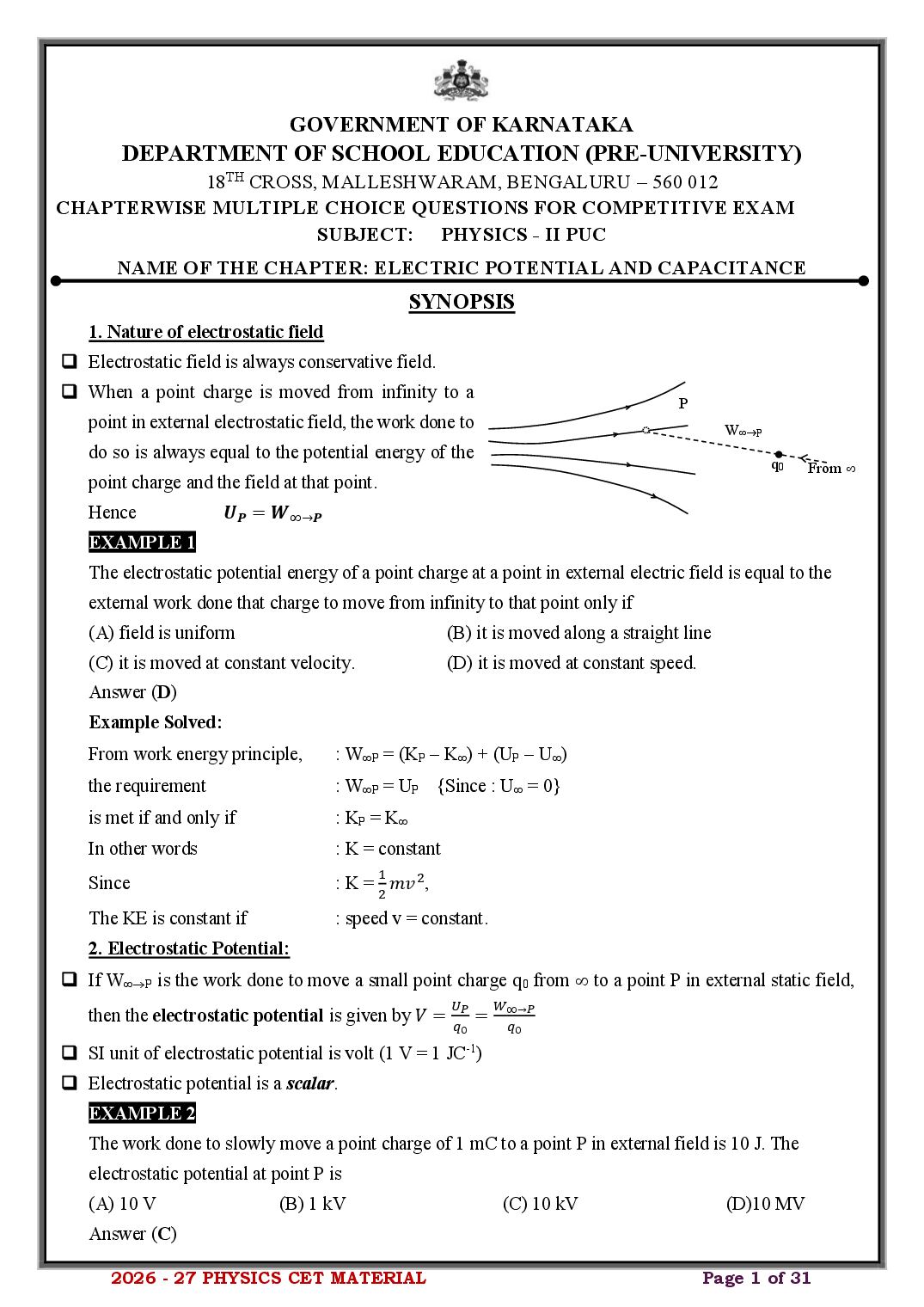
❑ When a point charge is moved from infinity to a
P
point in external electrostatic field, the work done to W→P
do so is always equal to the potential energy of the
q0 From
point charge and the field at that point.
Hence 𝑼𝑷 = 𝑾∞→𝑷
EXAMPLE 1
The electrostatic potential energy of a point charge at a point in external electric field is equal to the
external work done that charge to move from infinity to that point only if
(A) field is uniform (B) it is moved along a straight line
(C) it is moved at constant velocity. (D) it is moved at constant speed.
Answer (D)
Example Solved:
From work energy principle, : WP = (KP − K) + (UP − U)
the requirement : WP = UP {Since : U = 0}
is met if and only if : KP = K
In other words : K = constant
1
Since : K = 2 𝑚𝑣 2,
The KE is constant if : speed v = constant.
2. Electrostatic Potential:
❑ If W→P is the work done to move a small point charge q 0 from to a point P in external static field,
𝑈 𝑊∞→𝑃
then the electrostatic potential is given by 𝑉 = 𝑞𝑃 =
0 𝑞0
❑ SI unit of electrostatic potential is volt (1 V = 1 JC-1)
❑ Electrostatic potential is a scalar.
EXAMPLE 2
The work done to slowly move a point charge of 1 mC to a point P in external field is 10 J. The
electrostatic potential at point P is
(A) 10 V (B) 1 kV (C) 10 kV (D)10 MV
Answer (C)
2026 - 27 PHYSICS CET MATERIAL Page 1 of 31
Page 2
𝑊∞→𝑃
As per the formula :𝑉= 𝑞0
10
We have : 𝑉 = 1×10−3 = 10 𝑘𝑉
3. Electrostatic potential due to a point charge:
❑ The electrostatic potential at a point due to a point charge q is V
𝟏 𝒒 r
𝑽= q P
𝟒𝝅𝜺𝟎 𝒓
❑ The electrostatic potential at P due to a positive point charge +q is also positive.
❑ The electrostatic potential at P due to a negative point charge − q is also negative.
EXAMPLE 3
The charge magnitude of an isolated fixed point charge is doubled and the distance to a point from it is
quadrupled. Then the electric potential at that point
(A) doubles. (B) quadruples. (C) halves. (D) remains same.
Answer (C)
Example Solved:
1 𝑞
According to the expression for potential of point charge :𝑉 = 4𝜋𝜀 𝑟 ,
0
𝑞
we may write :𝑉∝𝑟
𝑉 𝑞 𝑟
Thus : 𝑛𝑒𝑤 = 𝑛𝑒𝑤 ×𝑟
𝑉 𝑞 𝑛𝑒𝑤
𝑉 2𝑞 𝑟 1 𝑉
Or : 𝑛𝑒𝑤 = 𝑞 × 4𝑟 = 2 → 𝑉𝑛𝑒𝑤 = 2
𝑉
EXAMPLE 4
V V − 2q V V
− 2q − 2q − 2q
q q q q
r r r
r
(B) (C) (D)
(A)
The variations of electrostatic potentials of a positive point charge q and negative point charge − 2q
are drawn with the distances r from them. The correct variation is shown in
Answer (C)
Example Solved:
1 𝑞
The electric potential due to +q is : 𝑉𝑞 =
4𝜋𝜀0 𝑟
1 2𝑞
The electric potential due to − 2q is : 𝑉−2𝑞 = − 4𝜋𝜀
0 𝑟
1
Hence, we find : Vq and V−2q 𝑟
2026 - 27 PHYSICS CET MATERIAL Page 2 of 31
Page 3
However, since : V-2q is –ve , V vs r variation graph must be in 4th quadrant
Secondly since : |V2q| = 2 |Vq| for a given separation,
the correct variation is shown in : choice (C)
4. Comparison between Electric field and Electrostatic potential due to a point charge
❑ The electric field due to a point charge is a vector, whereas electric potential is a scalar.
𝑞 𝑞
❑ The electric field at a point varies as 𝐸 ∝ 𝑟 2, whereas electrostatic potential varies as 𝑉 ∝ 𝑟 .
𝐹𝑂𝑅𝐶𝐸 𝑊𝑂𝑅𝐾
❑ The electric field is 𝐸 = 𝐶𝐻𝐴𝑅𝐺𝐸 , whereas potential 𝑉 = 𝐶𝐻𝐴𝑅𝐺𝐸
5. Electrostatic potential due to many point charges:
V here
❑ The electrostatic potential at a point due to point charges q i at distance ri from it
r3 P
is given by superposition principle:
q3 r2
𝑛
1 𝑞1 1 𝑞2 1 𝑞𝑛 1 𝑞𝑖 r1
𝑉= + +. . . + ⇔𝑉= ∑
4𝜋𝜀0 𝑟1 4𝜋𝜀0 𝑟2 4𝜋𝜀0 𝑟𝑛 4𝜋𝜀0 𝑟𝑖 q2
𝑖=1 q1
EXAMPLE 5
Three point charges +q, +q and − 2q are placed at (−a, 0), (0, a) and (a, 0) respectively. The
electrostatic potential at the origin is
1 4𝑞 1 𝑞 1 4𝑞
(A) 4𝜋𝜀 (B) 4𝜋𝜀 𝑎 (C) − 4𝜋𝜀 (D) zero
0 𝑎 0 0 𝑎
Answer (A)
Example Solved:
y
1
𝑞
The total electric potential at origin is : 𝑉 = 4𝜋𝜀 ∑𝑛𝑖=1 𝑟𝑖 +q
0 𝑖
+q a − 2q
1 𝑞 1 𝑞 1 2𝑞 x
Hence, : 𝑉 = 4𝜋𝜀 𝑎 + 4𝜋𝜀 𝑎−4𝜋𝜀 =0 a a
0 0 0 𝑎
6. Electrostatic potential due to a dipole:
❑ The electrostatic potential due to a dipole (of dipole length 2a) at points at large distances compared
with the dipole length is given by
𝟏 𝒑𝒄𝒐𝒔𝜽 𝟏 ⃗ .𝒓̂
𝒑
𝑽 = 𝟒𝝅𝜺 𝒓𝟐
⇔ 𝑽 = 𝟒𝝅𝜺 𝒓𝟐 if and only if r > > 2a.
𝟎 𝟎
Where p is the dipole moment of the dipole, is the angle between the dipole moment and the line
joining the point P to midpoint of the dipole and r is the length of that
P1
line. V
(1) The electric potential on the axial points for which r
𝟏 𝒑 Equatorial 𝑟Ƹ
(a) = 0, 𝑽 = 𝟒𝝅𝜺 𝒓𝟐 (at point P1) +q
𝟎 plane P3
𝟏 𝒑
−q
and (b) = 180, 𝑽 = − 𝟒𝝅𝜺 𝒓𝟐 (at point P2)
𝟎
(2) The electric potential on the equatorial point is P2
(a) = 90, V = 0 (at point P3)
2026 - 27 PHYSICS CET MATERIAL Page 3 of 31
Page 4
The electric potential at a point A around an electric dipole of dipole length 2a at distance 20a and
angular position (relative to its dipole moment) of 30 is V1. The electric potential at a point B around
the same electric dipole at distance 40a and angular position of 60 is V2. Then
(A) V1 = 4√3V2 (B) V1 = 3√4V2 (C)V1 =√3V2 (D) V1 = 2V2
Answer (A)
Example Solved:
1 𝑝 𝑐𝑜𝑠 𝜃 𝑐𝑜𝑠 𝜃
The electric potential of the dipole is : 𝑉 = 4𝜋𝜀 ⇒𝑉∝
0 𝑟2 𝑟2
𝑉 𝑐𝑜𝑠 𝜃 𝑟2
Hence : 𝑉1 = 𝑐𝑜𝑠 𝜃1 × 𝑟22
2 2 1
𝑉 𝑐𝑜𝑠 30° 40𝑎 2
Substituting the relevant values : 𝑉1 = 𝑐𝑜𝑠 60° × (20𝑎) = 4√3 → 𝑉1 = 4√3𝑉2 .
2
7. Electrostatic potential due to a charged spherical conductor
❑ The electrostatic potential due to a charged spherical shell of charge Q and P1
radius R is P2
O r
𝟏 𝑸
𝑽= inside it, i.e., for r ≤ R (at P1). R
𝟒𝝅𝜺𝟎 𝑹
𝟏 𝑸
and 𝑽 = 𝟒𝝅𝜺 𝒓 outside it, i.e., for r > R (at P2).
𝟎
EXAMPLE 7
The electrostatic potential at a point 20 cm radially away from the center of a charged spherical
conductor of radius 10 cm is 10 kV. The surface charge density of the sphere is (Take 0 = 9 10-12
SIU)
(A) 22.5 nC/m2 (B) 36 nC/m2 (C) 0.36 C/m2 (D) 1.8 C/m2
Answer (D)
Example Solved:
Since : r = 20 cm and R = 10 cm,
the point is : outside the spherical conductor.
1 𝑄 𝑄
Since the electric potential due to spherical conductor is: 𝑉 = , ( = 𝜎)
4𝜋𝜀0 𝑟 4𝜋𝑅2
1 𝑄 𝑅2
: 𝑉 = 𝜀 4𝜋𝑅2 × 𝑟
0
𝑟
we get : = 0V × 𝑅2
0.2
Hence : = (910−12)(104) × 0.12 =1.8 C/m2
8. Potential difference and work done to move a charge in terms of potential difference:
❑ If q0 is the test charge, in order to take that charge slowly from B to A, the work done W B →A per charge
q0 is called the potential difference between A and B.
𝑾𝑩→𝑨
Hence potential difference (pd) 𝑽𝑨 − 𝑽𝑩 = 𝒒𝟎
Conversely, the work done to move the charge from B to A is 𝑾𝑩→𝑨 = 𝒒𝟎 (𝑽𝑨 − 𝑽𝑩 ).
2026 - 27 PHYSICS CET MATERIAL Page 4 of 31
Page 5
When a charged particle having mass 2 g and charge 0.001 C is taken from a point a to another point b
in external electric field slowly, the work done is 2 J. The potential difference between the two points
is
(A) 2 V (B) 200 V (C) 2000 V (D) 20,000 V
Answer (C)
Example Solved:
𝑊𝐵→𝐴
As per the formula : VA − VB = 𝑞0
2𝐽
we have : VA − VB = 0.001𝐶 = 2 𝑘𝑉
EXAMPLE 9
A point charge is moved from a point having potential 3 kV to another point having potential 2 kV.
The work done in doing so is − 2 J. The change is then
(A) 0.001 C (B) 0.002 C (C) 0.003 C (D) − 0.002 C
Answer (B)
Example Solved:
𝑊𝐵→𝐴
From the expression : 𝑉𝐴 − 𝑉𝐵 = 𝑞0
,
𝑊
We may write : 𝑞0 = 𝑉 𝐵→𝐴
𝐴−𝑉 𝐵
−2
Or : 𝑞0 = (2−3)×103 = 0.002 𝐶
9. Equipotential surfaces (EPS) and relation between ⃗𝑬and V.
❑ Surfaces either imaginary or real on which the potential at every point on them is identical are called
equipotential surfaces.
Equipotential surfaces due to
(a) an isolated point charge (b) infinite line charge (c) infinite charged sheet
→
E →
Q E
EPS : Family of
Concentric Spheres
EPS : Family of
EPS : Family of parallel planes
Coaxial cylinders
❑ Properties of equipotential surfaces
(1) The direction of the electric field is always perpendicular to the EPS.
(2) The work done to move a point charge from one point to another on a given EPS is always zero.
2026 - 27 PHYSICS CET MATERIAL Page 5 of 31
Page 6
distance l, then the electric field at that point is
⃗𝑬 = − (𝜹𝑽) 𝒏
̂
𝜹𝒍
where 𝑛̂is the unit vector in the decreasing direction of the potential.
In general ⃗𝑬 = − 𝝏𝑽 𝒊Ƹ − 𝝏𝑽 𝒋Ƹ − 𝝏𝑽 𝒌
̂
𝝏𝒙 𝝏𝒚 𝝏𝒛
(4) No two EPS can intersect.
(5) The direction of the electric field is along the direction of steepest decrease of potential.
EXAMPLE 10
Three equipotential surfaces with their respective potentials are as shown. A point i
charge having charge of 10 C is taken from i to f. The work done to move that f
charge is
− 20 V − 40 V − 60 V
(A) + 2 mJ (B) 0.2 J (C) − 0.2 mJ (D) − 2 J
Answer (C)
Example Solved:
The potential difference between i and f is : Wi→f = q0 (Vf − Vi)
Hence : Wi→f = (10 10−6) {(−40) − (−20)} = − 0.2 mJ
EXAMPLE 11
The potential in a region of space is variable along the x axis according to the equation
V = 2x2 + 3x + 1
where x is in meter and V is in volt. The magnitude of the electric field (in Vm -1) at x = 1 m is
(A) 4 (B) 3 (C) 1 (D) 7
Answer (D)
Example Solved:
The relation between the electric field
𝑑𝑉
and electric potential is given by : E = − 𝑑𝑥
𝑑
Hence : E = − 𝑑𝑥 (2𝑥 2 + 3𝑥 + 1) = − 4x − 3
At x = 1 m : |Ex = 1| = |− 4(1) − 3|= 7 Vm-1
10. Potential energy of a system of charges in the absence of external electric field:
❑ If q1, q2 and q3 are the three point charges separated from each other q2
by distances r12, r23 and r13 as shown, then the total potential energy
(PE) in the absence of external electric field is given by r23
r12
𝟏 𝒒𝟏 𝒒𝟐 𝒒𝟐 𝒒𝟑 𝒒𝟏 𝒒𝟑 q3
𝑼= ( + + )
𝟒𝝅𝜺𝟎 𝒓𝟏𝟐 𝒓𝟐𝟑 𝒓𝟏𝟑 r13
q1
❑ If only two charges q1 and q2 are separated by a distance r from each
other, then the PE of the system is
𝟏 𝒒𝟏 𝒒𝟐
𝑼 = 𝟒𝝅𝜺 .
𝟎 𝒓
2026 - 27 PHYSICS CET MATERIAL Page 6 of 31
Page 7
Three point charges q, − q and Q are at the corners A, B and C respectively of an isosceles triangle
ABC, with AB = BC and AC = √2 AB. The total electric potential energy of the system is zero. Then
the relation between q and Q is
√2 √2 √2−1 √2
(A) 𝑄 = −𝑞 ( 2−1) (B) 𝑄 = −𝑞 ( 2+1) (C) 𝑄 = −𝑞 ( ) (D) 𝑄 = 𝑞 ( 2−1)
√ √ √2 √
Answer (A)
Example Solved: A q
1 𝑞(−𝑞) 𝑞𝑄 (−𝑞)𝑄 √2r
The PE of the three charge system is zero : 4𝜋𝜀 [ + 2𝑟 + ]=0 r
0 𝑟 √ 𝑟
Q
B
−q r C
𝑄
Or :−q+ −Q=0
√ 2
√2
Solve for Q : 𝑄 = −𝑞 ( 2−1)
√
11. Potential energy of a system of two charges in the presence of external electric field:
❑ If V1 and V2 are the potentials at points a and b in the external
V1 here
electric field, if q1 and q2 are the two point charges at a and b then
a q1
the PE of the system is r
𝑼 = 𝒒𝟏 𝑽𝟏 + 𝒒𝟐 𝑽𝟐 + 𝟒𝝅𝜺
𝟏 𝒒𝟏 𝒒𝟐 q2
b V2 here
𝟎 𝒓
EXAMPLE 13
Uniform electric field |E|= 200 kV/m exists along the +x axis. The potential at x = 0 is V = 0. Two
point charges 1 C and − 2 C are at x = 1 m and x = 2 m respectively. The PE of the system of
charges is
(1) +182 mJ (2) − 182 mJ (3) 382 mJ (4) − 382 mJ
Answer (1)
Example Solved:
Since the electric field is constant: V(x) – Vref = − E (x – xref)
Substituting the fact that : when xref = 0 → Vref = 0,
we get : V(x) = − Ex = − (200 103)x
The potential at : x = 1 m, V1 = V(1) = − (200 103)(1) = − 200 kV
and at : x = 2 m, V2 = V(2) = − (200 103)(2) = − 400 kV
1 𝑞1 𝑞2
Hence : U = q1V1 + q2V2 +
4𝜋𝜀0 𝑟
(10−6 )(−2×10⁻⁶ )
gives : U = (10-6) (−2 105) + (−2 10-6) (−2 105) +(9 × 10⁹ ) 1
U = +182 mJ.
2026 - 27 PHYSICS CET MATERIAL Page 7 of 31
Page 8
If p is the dipole moment of a dipole in an external electric
→ +q →
p
field, is the angle between the directions of the electric field E
E and the dipole moment, then the PE of the dipole is −q
⃗⃗ = −𝒑𝑬 𝒄𝒐𝒔 𝜽
⃗ .𝑬
𝑼 = −𝒑
Case (i): When = 0, Umin = − pE
→
p →
→ STABLE EQUILIBRIUM. p
→
E →
Case (ii): When = 90, U=0 E
0
→ NO EQUILIBRIUM. →
p 90
Case (iiI): When = 180, Umax = pE →
E
→ UNSTABLE EQUILIBRIUM. 180
EXAMPLE 14
An electric dipole placed in an external uniform electric field at an angular position experiences a
torque and possesses a potential energy of magnitude of U. Then the ratio of U to is
(A) sec (B) cosec (C) tan (D) cot
Answer (D)
Example Solved:
The torque acting on the dipole is : = pE sin
The PE of the dipole in the same angular position is : U = pE cos
𝑈 𝑝̸ 𝐸 ̶̸ 𝑐𝑜𝑠 𝜃
Hence the required ratio is : 𝜏 = 𝑝̸ 𝐸̸ 𝑠𝑖𝑛 𝜃 = 𝑐𝑜𝑡 𝜃
13. Electrostatics of conductors:
(1) Inside a conductor, electrostatic field is zero. Eins = 0.
(2) At the surface of a charged conductor, electrostatic field must be normal to the surface at every
point.
(3) The interior of a conductor can have no excess charge in the static situation.
(4) Electrostatic potential is constant throughout the volume of the conductor and has the same value
(as inside) on its surface.
𝜎
(5) Electric field at the surface of a charged conductor is 𝐸⃗ = 𝜀 𝑛̂.
0
EXAMPLE 15
An egg shaped copper conductor is given some charge. The electric
•3
fields at points 1, 2, 3 and 4 (with points 1 and 2 lying inside it) are
indicated as E1, E2, E3 and E4. Then •1
•4
(A) E1 = E2 0 and E1 > E2 but E3 = E4 = 0.
•2
(B) E1 = E2 = 0 and E3 E4 > 0 but E3 > E4
(C) E1 = E2 = 0 and E3 E4 > 0 but E3 < E4
(D) E1 > E2 > E3 > E4.
Answer (C)
2026 - 27 PHYSICS CET MATERIAL Page 8 of 31
Page 9
As per the property #1, : the electric field inside the charged conductor is zero.
Thus : E1 = E2 = 0
The points : 3 and 4 lie outside.
Hence : E3 E2 0
Since we know that : the electric field is stronger at sharper points,
we have : E3 < E4.
EXAMPLE 16
The electric potential due to an irregularly shaped charged conductor is V (in V)
drawn as follows. If r = 0 is taken at its center of mass, the size of the
conductor is of the order of
(A) 2a (B) 3a
(C) 4a (D) a/2
a 2a 3a 4a r(in SIU)
Answer (C)
Example Solved:
As per the property #4, : V is constant throughout the charged conductor and has a
value equal to that on the surface.
Outside the conductor, : V varies.
From the diagram, it is clear that : from r = 0 to r = 2a, V = constant;
and beyond : r = 2a, V varies.
Hence the size of the conductor : size 2 2a = 4a.
EXAMPLE 17
Points A and B lie very near but outside an irregularly shaped charged •A
conductor as shown. The electric field at A has a magnitude of 20 N/C. If
surface charge densities at A and B are A and B,
•B
(A) A = B = 200. (B) A = 200 B but B < A.
(C) A = 200 B but B > A. (D) A = 100 B but B > A.
Answer (C)
Example Solved:
We know that : sharper the points, more crowded is the charge distribution.
Hence : B A and B > A.
𝜎
Secondly since : EA = 𝜀𝐴 ,
0
we get : A = EA0 = 20 0 = 200.
14. Polar and Non polar molecules
❑ Molecules whose positive and negative charge centers DO NOT coincide are called polar molecules.
Eg.,: HCl molecule, and H2O molecule.
❑ Molecules whose positive and negative charge centers COINCIDE are called non polar molecules.
Eg.,: CO2 molecule, and H2 molecule.
2026 - 27 PHYSICS CET MATERIAL Page 9 of 31
Page 10
Polar dielectrics in the external electric field Non polar dielectrics in the external electric field
In the absence of field In the presence of field In the absence of field In the presence of field
EXAMPLE 17
A polar dielectric slab is placed in external uniform electric field parallel to four of its sides. Then the
slab
(A) experiences a net force in the direction of the field
(B) experiences a torque which tends to rotate it clockwise
(C) experiences a torque which tends to rotate anticlockwise.
(D) only gets polarized with a net +ve and –ve charges appearing on two faces of the slab.
Answer (D)
Example Solved:
Referring to the diagram, we find that the slab neither experiences a net force or torque. It gets only
polarized.
The net charge inside
Net positive charge appears here
this is zero
Net negative charge appears
here
❑ If 𝑝 is the total dipole moment of the dielectric slab and V is its volume, then we define
polarization ⃗⃗ = ∑𝒑⃗.
𝑷
𝑽
2
❑ The SI unit of polarization is C/m .
❑ For an isotropic dielectric, the polarization ∝ electric field strength.
Or 𝑃⃗ ∝ 𝐸⃗ ⟹ 𝑷
⃗⃗ = 𝝌𝒆 𝜺𝟎 𝑬
⃗
where e is called the electric susceptibility.
16. Capacitance and Capacitors:
❑ If Q is the charge on a conductor and V is the potential on it (relative to potential at infinity), the
capacitance C is given by
𝑸
𝑪=𝑽
❑ The SI unit of capacitance is farad (F).
2026 - 27 PHYSICS CET MATERIAL Page 10 of 31
Page 11
See figure (a).
b a d
+Q
b A
R L +Q
a −Q
−Q
Fig (a) Fig (b) Fig (c) Fig (d)
❑ The capacitance of a
spherical conductor having inner radius a and outer radius b is given by
𝟒𝝅𝜺
𝑪 = 𝟏 𝟏𝟎 .
− −
𝒂 𝒃
See figure (b).
❑ The capacitance of a cylindrical conductor having inner radius a and outer radius b is given by
𝟐𝝅𝜺𝟎 𝑳
𝑪= .
𝒍𝒏(𝒃/𝒂)
See figure (c).
❑ The capacitance of a parallel plate air capacitor of plate area A and plate separation d is
𝜺 𝑨
𝑪 = 𝟎𝒅 . See figure (d).
EXAMPLE 18
The variation of capacitance of a parallel plate capacitor with plate area and plate separation is best
shown in
C C C C C C C C
A d A d A d A
d
(A) (B) (C) (D)
Answer (C)
Exercise Solved:
From the expression of the capacitance of
𝜀 𝐴
l plate capacitor is : 𝐶 = 0𝑑
𝐴
Hence :𝐶∝𝑑
Thus as : A increases, C should increase linearly as ,
and as : d increases, C should drop as .
17. Capacitor Combinations:
(a) Series combination
❑ When n capacitors C1, C2, C3,……., Cn are connected in series, the effective capacitance is given by
𝟏 𝟏 𝟏 𝟏
= + +. . . . . . . . . . . . . +
𝑪𝒔 𝑪𝟏 𝑪𝟐 𝑪𝒏 Cn
C1 C2 C3
❑ When only two capacitors C1 and C2 are connected in
series,
𝑪 𝑪 C1 C2
𝑪𝒔 = 𝑪 𝟏+𝑪𝟐
𝟏 𝟐
2026 - 27 PHYSICS CET MATERIAL Page 11 of 31
Page 12
𝑪
𝑪𝒔 = 𝒏
C C C C
❑ When two capacitors are connected in series, the p.d across C 1 in terms of total p.d across the
combination is given by
𝑪𝟐
𝑽𝟏 = ×𝑽 V1 V2
𝑪𝟏 +𝑪𝟐
𝑪 C1 C2
Similarly, the p.d across C2 is given by 𝟏
𝑽𝟐 = 𝑪 +𝑪 ×𝑽 V
𝟏 𝟐
(b) Parallel combination
C1
❑ When n capacitors C1, C2, C3,……., Cn are connected in parallel, the effective
C2 C2
capacitance is given by
𝑪𝑷 = 𝑪𝟏 + 𝑪𝟐 +. . . . . . . . . . . . . +𝑪𝒏 C1
❑ When only two capacitors C1 and C2 are connected in parallel,
Cn
𝑪𝑷 = 𝑪𝟏 + 𝑪𝟐 C2 C
❑ When n capacitors all having C are connected in parallel, the effective capacitance is C
𝑪𝒔 = 𝒏𝑪 C
❑ When two capacitors are connected in parallel, the charge on C 1 in terms of total charge of the
combination is given by
𝑪𝟏 C1
𝑸𝟏 = ×𝑸
𝑪𝟏 + 𝑪𝟐 + Q1 − Q1
Q
𝑪 − Q2
Similarly, the charge on C2 is given by 𝟐
𝑸𝟐 = 𝑪 +𝑪 ×𝑸 +Q2
𝟏 𝟐 C2
EXAMPLE 19
A total of n capacitors each having capacitance C are connected in series and then connected in
parallel. The ratio of their effective capacitance in parallel to that in series is drawn on a graph against
n2. Then the resulting graph is a/an
(A) upward slanted straight line (B) parabola symmetric with horizontal axis
(C) parabola symmetric with vertical axis (D) downward slanted straight line
Answer (A)
Example Solved:
Using the fact that : Cs = C/n CP/Cs
and : CP = C n,
𝐶 𝑛𝐶
we get : 𝐶𝑃 = 𝐶/𝑛 = 𝑛2 n2
𝑆
If we take : Cp/CS = y and n2 = x,
we get : Cp/CS vs n2 variation similar to y = x variation.
Hence the graph : is an upwardly slanted straight line.
2026 - 27 PHYSICS CET MATERIAL Page 12 of 31
Page 13
The effective capacitance (of the circuit shown) across a and b is 4 F
6 F
(A) (124/13) F (B) 3 F
a 3 F b
(C) 19 F (D) 5 F 6 F
Answer (B)
Example Solved: 4 F
6 F
The highlighted capacitors : 3 F and 6 F are in series. a 3 F b
3×6
Hence effective capacitance of them : 𝐶1 = 3+6 = 2𝜇𝐹 6 F
Now, the highlighted capacitors : 4 F and 2 F are in parallel.
4 F
Hence their effective capacitance is : 𝐶2 = 2 + 4 = 6𝜇𝐹 6 F
a b
Finally, the two highlighted : 6 F capacitors are in series. 2 F
Hence the effective capacitance across
6×6 a b
a and b : 𝐶𝑎𝑏 = 6+6 = 3 𝜇𝐹
6 F 6 F
18. Energy Stored in Capacitors:
❑ If a capacitor of capacitance C is charged to a p.d of V, the energy stored in it in the form of electrostatic
potential energy is
𝟏 𝟐
𝑼= 𝑪𝑽
𝟐
❑ If Q is the magnitude of charge on each plate of that capacitor, then the energy stored in the capacitor
can be rewritten as
𝟏
𝑼= 𝑸𝑽
𝟐
𝟏 𝑸𝟐
❑ Similarly we may rewrite the above expression as 𝑼 = 𝟐 𝑪 .
18a. Energy density:
❑ If U is the potential energy stored in the capacitor, V is the volume enclosed by the two conductors of
𝑼
the capacitor, then the energy density is given by 𝒖𝑬 = 𝑽 .
❑ If E is the electric field strength inside the region bounded by the two conductors of the capacitors, then
𝟏
we may write 𝒖𝑬 = 𝟐 𝜺𝟎 𝑬𝟐 .
EXAMPLE 21
An air parallel plate capacitor having plate area 2 cm 2 and plate separation 2 mm is charged by a 10 V
battery. The energy stored in the capacitor and energy density are respectively (both in SIU)
(A) 0.10, 1.250 10−7 (B) 0.10, 1.250 107
(C) 0, 12.50 10−7 (D) 0.10, 1250 10−7
Answer (B)
2026 - 27 PHYSICS CET MATERIAL Page 13 of 31
Page 14
𝜀 𝐴 𝜀 ×2×10⁻⁴
The capacitance of the capacitor is : C = 0𝑑 = 02×10−3 = 0.10 in SIU
The volume bounded by the capacitor plates : V = Ad = (2 10-4) (2 10-3) = 4 10-7 in SIU
1 1
The energy stored in the capacitor : U = 2CV2 = 2 0.10 102 = 50 in SIU
𝑈
The energy density is thus : uE = 𝑉 = 50/(4 10-7) = 1.250 107 in SIU
********
2026 - 27 PHYSICS CET MATERIAL Page 14 of 31
Page 15
1. The electric field and the electric potential at a point due to a point charge are 16 N/C and 8 J/C
respectively. The magnitude of the charge and the distance of the point from the charge respectively are
(A) 4.44 × 10⁻¹⁰ C, 0.5 m (B) 4.44 × 10⁻¹⁰ C, 2 m
(C) 8.89 × 10⁻¹⁰ C, 0.5 m (D) 8.89 × 10⁻¹⁰ C, 0.5 m
2. Four point charges of +10 C, –5 C, +10 C and –5 C are placed at the positions of numbers of 1, 3, 7
and 9 of a clock. If E and V are the electric field and electric potential at the centre, then
(A) E 0, V 0 (B) E = 0, V 0 (C) E 0, V = 0 (D) E = 0, V = 0
3. Ten electrons are equally spaced and fixed around a circle of radius R. Relative to V = 0 at infinity, the
electrostatic potential V and the electric field E at the centre C are
(A) E 0, V 0 (B) E = 0, V 0 (C) E 0, V = 0 (D) E = 0, V = 0
4. The values of electric field (E) and electric potential (V) at any point on the equatorial plane of an electric
dipole are such that
(A) E = 0 and V = 0 (B) E = 0 and V ≠ 0 (C) E ≠ 0 and V = 0 (D) E ≠ 0 and V ≠ 0
5. 5 J of work is done to transfer 2mC of charge from point A to point B. 16 J of work is done to transfer
4mC of charge from point C to point D. Then the ratio of the potential differences between the pairs of
points respectively is
(A) 5:2 (B) 2:5 (C) 8:5 (D) 5:8
6. The distance between the two point charges +5 C and –3C is 40 cm. At what point on the line joining
the two charges, the electric potential due to these two charges will be zero?
(A) At a distance of 25 cm from 5 C (B) At a distance of 15 cm from 5 C
(C) At a distance of 10 cm from 5 C (D) At a distance of 25 cm from –3 C
7. The graph plotted between electric potential (V) and distance (r) for a uniformly charged conducting sphere
of radius (R) is
8. A hollow sphere of radius r is put inside another hollow sphere of radius R.
The charges on the two are + Q and –q as shown in the adjacent figure. A point
P is located at a distance x from the common centre O such that r < x < R. The
electric potential at the point P is
1 Q−q 1 Q q
(A) (B) −
4π0 x 4 πε 0 R r
1 Q q 1 1 Q
(C) − (D) .
4 πε 0 R x 4 πε 0 4 πε 0 x
2026 - 27 PHYSICS CET MATERIAL Page 15 of 31
Page 16
the shell. The electrostatic potential at a point P a distance R from the centre O of the shell is
2
(q + Q) 2 2Q 2Q 2q 2Q q
(A) (B) (C) − (D) +
40 R 4 0 R 4 0 R 4 0 R 4 0 R 4 0 R
10. Four point charges +q, +2q, –q and –q are placed respectively at the corners A, B, C and D of a square
ABCD of side a. The electric potential at the centre O of the square is
1 q 1 2q 1 2q 1 4q
(A) (B) . (C) . (D) .
4 π ε0 a 4 π ε0 a 4 π ε0 a 4 π ε0 a
11. A positively charged conductor-A is brought near a negatively charged conductor-B. The potential of B
(A) becomes zero (B) remains constant (C) increases (D) decreases
12. 64 identical mercury droplets each charged q and having same potential V, coalesce to form a single bigger
drop. The potential of the bigger drop will be
(A) V (B) 4V (C) 16V (D) 64V
13. The work done in moving a point charge between two points on the perpendicular bisector of an electric
dipole
(A) depends on the magnitude of the charges
(B) depends on the distance through which the charge is moved
(C) depends on the distance between the equal and opposite charges
(D) zero
14. Two metal spheres of radii R1 and R2 are charged to the same potential. The ratio of charges on the spheres
is
2 2 3 3
(A) R1 : R 2 (B) R1 : R2 (C) R1 : R2 (D) R1 : R 2
15. An infinite number of charges each 1 C, are placed on the x-axis at co-ordinates x = 1 m, 2 m, 4 m, 8 m,
….... What is the net electric potential at origin O?
(A) 3.6 kV (B) 9 kV (C) 13.5 kV (D) 18 kV
16. As shown in the figure, charges +q and -q are placed at the vertices B and C of an isosceles triangle. The
potential at the vertex A is A
1 2q
(A) 4 . (B) Zero a
0 a + b2
2
b b
1 q 1 (−q)
(C) . (D) . B C
4 0 a2 + b 2 4 0 a2 + b 2 +q –q
17. The radius of a soap bubble whose potential is 16V is doubled. The new potential of the bubble will be
(A) 2V (B) 4V (C) 8V (D) 16V
18. A conducting sphere of radius R has surface charge density 𝜎. The electric potential on its surface is
(A) 𝜎R/𝜀0 (B) 𝜎R𝜀0 (C) R/𝜎𝜀0 (D) 𝜎/R𝜀0
2026 - 27 PHYSICS CET MATERIAL Page 16 of 31
Page 17
Assertion : Electrons move from low potential to high potential region.
Reason : Electron has negative charge.
(A) Both assertion and reason are true and the reason is the correct explanation of the assertion.
(B) Both assertion and reason are true but reason is not the correct explanation of the assertion.
(C) Assertion is true but reason is false.
(D) Assertion and reason both are false.
20. Match the following Column-I with Column-II.
Column-I Column-II
(i) Electrical capacitance (a) [M–1 L–3 T4 A 2]
(ii) Permittivity of free space (b) [M1 L2 T–3 A –1 ]
(iii) Electrical potential (c) [M1 L2 T–2]
(iv) Electrostatic potential energy (d) [M–1 L–2 T4 A 2]
(A) i-a, ii-d, iii-b, iv-c (B) i-d, ii-a, iii-b, iv-c
(C) i-d, ii-a, iii-c, iv-b (D) i-a, ii-d, iii-c, iv-b
21. In hydrogen atom, the electron revolves around the nucleus in an orbit of radius 0.53 Å. Then the electric
potential produced by the nucleus at the position of the electron is
(A) – 13.6 V (B) – 27.2 V (C) 27.2 V (D) 13.6 V
22. The electrostatic potential on the surface of a charged conducting sphere is 1000 V. Two statements are
made in this regard:
Statement-I: At any point inside the sphere, electric field is zero.
Statement-II: At any point inside the sphere, the electrostatic potential is 1000 V.
(A) Both statements are true. (B) Statement-I is true and Statement-II is false.
(C) Both statements are false. (D) Statement-I is false and Statement-I is true.
23. If a charge is moved from one point to the other over an equipotential surface then work done is
(A) positive (B) negative (C) zero (D) not defined
24. Identify the correct statement regarding an equipotential surface.
(A) Equipotential surfaces for a uniform electric field are spheres.
(B) Electric field is always parallel to the equipotential surface.
(C) Work done to move a charge on an equipotential surface is not zero.
(D) Equipotential surfaces are those surfaces where the potential remains constant at every point.
𝐸
25. The ratio of electric field and potential (𝑉) at a mid-point of the electric dipole having the dipole length 𝑙
1
(A) 𝑙 (B) 2𝑙 (C) 𝑙 (D) infinity
26. Charge 2𝑞, −𝑞 𝑎𝑛𝑑 − 𝑞 lie at the vertices of an equilateral triangle. The values of 𝐸 𝑎𝑛𝑑 𝑉at the centroid
of the triangle will be
(A) 𝐸 = 0, 𝑉 = 0 (B) 𝐸 = 0, 𝑉 ≠ 0 (C) 𝐸 ≠ 0, 𝑉 = 0 (D) 𝐸 ≠ 0, 𝑉 ≠ 0
2026 - 27 PHYSICS CET MATERIAL Page 17 of 31
Page 18
+q +q
−q +q 𝐸⃗ 𝐸⃗ +q −q
𝐸⃗ −q 𝐸⃗
−q
(A) (B) (C) (D)
28. At a certain distance from a point charge the electric field is 500 𝑉/𝑚.The potential at that point is 3000𝑉.
The distance from the point charge is
(A) 144 𝑚 (B) 6 𝑚 (C) 12𝑚 (D) 36𝑚
29. An electric dipole experiences maximum torque when placed in a uniform electric field. At this orientation,
its potential energy is:
(A) Maximum (B) Minimum (C) Zero (D) Infinite
30. Let V be the electric potential at a point. Then the electric field E, along the x-direction at the point is given
by
𝑑𝑉 𝑑𝑉 𝑑𝑉 𝑑𝑉
(A) −𝑉 𝑑𝑥 (B) − 𝑑𝑥 (C) 𝑑𝑥 (D) 𝑉 𝑑𝑥
31. The points resembling equal potentials are S
(A) P and Q (B) S and Q P Q
(C) S and R (D) P and R R
32. An electric dipole of dipole moment p is aligned parallel to a uniform electric field E. The energy required
to rotate the dipole by 60° is
𝑝𝐸 𝑝𝐸
(A) 𝑝𝐸 (B) 2 (C) − 2 (D) −𝑝𝐸
33. The below figure shows equipotential surfaces. The direction of electric
R −30V
field 𝐸 at points P and R is −25V −20V
−15 V
(A) At P, E is to the left. At R, E is upward −10 V
(B) At P, E is to the right. At R, E is downward
(C) At P, E is to downward. At R, E is to the left P
(D) At P, E is to upward. At R, E is to the right
34. What is the work done in moving a 2𝜇𝐶 point charges from corner A to corner B A B
(2 C)
of a square ABCD in figure when a10𝜇𝐶charge exists at the centre of the square?
(A) 5 𝐽 (B) zero (10 C)
(C) 2 𝐽 (D) 20𝐽 D C
35. Statement:-1 The work done to move a charge anywhere along an equipotential surface is zero,
Statement:-2 Two distinct equipotential surfaces never intersect each other
Select the correct option:
(A) Both Statement I and Statement II are true.
(B) Both Statement I and Statement II are false.
(C) Statement I is true but Statement II is false.
(D) Statement I is false but Statement II is true.
2026 - 27 PHYSICS CET MATERIAL Page 18 of 31
Page 19
position 𝑥, match the column -1 with Colum -2
Column-1 Column-2
1) Potential at 𝑥 = 1 𝑚 a) Zero
2) potential at 𝑥 = 4 𝑚 b) 10 V
3) electric field at 𝑥 = 4.5 𝑚 c) 5 V
4) electric field at 𝑥 = 0.5 𝑚 d) –10 V
(A) 1- d, 2-c, 3-b,4-a
(B) 1-b, 2-a, 3-c, 4-d
(C) 1-b, 2-a, 3-d, 4-c
(D) 1-b, 2-c, 3-a, 4-d
37. Electric potential at a point is 𝑉 = −5𝑥 + 3𝑦 + √15 𝑧, then the magnitude of electric field is
(A) 7 (B) −2 + √15 (C) √2 (D) +2 − √15
38. The potential energy of a charge and a dipole is below figure. 𝑎
1 𝑝𝑞 1 𝑝𝑞
(A) − 4𝜋 𝜀 𝑎2 (B) + 4𝜋 𝜀 𝑎2
0 0 𝑞 𝑝
1 𝑞 1 𝑝
(C) 4𝜋 𝜀 𝑎2 (D) 4𝜋 𝜀 𝑎2
0 0
39. An electric dipole of length 20cm having ±3 × 10⁻³ 𝐶 charge placed 600 with respect to a uniform
electric field experiences a torque of magnitude 6 𝑁𝑚. The potential energy of the dipole is
(A) 3√5 𝐽 (B) 5√3 𝐽 (C) −3√2 𝐽 (D) −2√3 𝐽
40. Which of the following statements is true about the relation between electric field and potential?
(A) Electric field is in the direction in which the potential decreases steepest
(B) The magnitude of electric field is given by the change in magnitude of potential per unit
displacement normal to the equipotential surface at that point.
(C) In the region of strong electric field, equipotential surfaces are far a apart.
(D) Both statements (A) and (B) are correct
41. An electric dipole consisting of charges +q and –q separated by a distance L is in stable equilibrium in a
uniform electric field E. The electrostatic potential energy of the dipole is
(A) 𝑞𝐿𝐸 (B) −𝑞𝐿𝐸 (C) 𝑧𝑒𝑟𝑜 (D) −2𝑞𝐿𝐸
42. An electric dipole moment 𝑝 is placed in a uniform electric field 𝐸⃗ . Then
(i) the torque on the dipole is 𝑝 × 𝐸⃗ ,
(ii) the potential energy of the system is − 𝑝 ∙ 𝐸⃗ and
(iii) the resultant force on the dipole is zero. Choose the correct option
(A) (i), (ii) and (iii) are correct (B) (i) and (iii) are correct and (ii) is wrong
(C) only (i) is correct (D) (i) and (ii) are correct and (iii) is wrong
43. A system of two charges separated by a certain distance apart has some electrostatic potential energy. If the
distance between them is increased, the potential energy of the system,
(A) may increase or decrease (B) remains the same
(C) increases in any case (D) decreases in any case
2026 - 27 PHYSICS CET MATERIAL Page 19 of 31
Page 20
(A)The electric potential energy of a system of two protons shall increase if the separation between
the two is decreased
(B)The electric potential energy of a proton-electron system will increase if the separation between the
two is decreased
(C)The electric potential energy of a proton-electron system will increase if the separation between the
two is increased
(D)The electric potential energy of a system of two electrons shall increase if the separation between
the two is decreased
45. Each corner of a cube of side l has a charge –q. The electrostatic potential energy of a charge q at the centre
of the cube is
4q 2 3 q2 4q 2 − 4q 2
(A) − (B) − (C) (D)
2 0l 4 0 l 2 0 l 3 0 l
46. If two electrons are approaching each other, the potential energy of the system will
(A) increase (B) decrease (C) remain constant (D) become zero
47. Two-point charges 𝐴 = +3 𝑛𝐶 and 𝐵 =1 𝑛𝐶 are placed 5 𝑐𝑚 apart in air. The work done to move charge 𝐵 towards
𝐴 by 1 𝑐𝑚 is
(A) 2.0×10⁻⁷𝐽 (B) 1.35×10⁻⁷𝐽 (C) 2.7×10⁻⁷𝐽 (D) 12.1×10⁻⁷𝐽
48. Three particles, each carrying a charge 10 µC are placed at the corners of an equilateral triangle of side 10
cm. The electrostatic potential energy of the system is
(A) 27 J (B) zero (C) 100 J (D) infinite
49. The charges Q, +q and +q are placed at the vertices of an equilateral triangle of side l. If the net electrostatic
potential energy of the system is zero, then Q is equal to
(A) q/2 (B) zero (C) –q/2 (D) –q
50. Three point charges 1 C, 2 C and 3 C are placed at the vertices of an equilateral triangle of side 1 m. The
work done to move these charges on to the vertices of a smaller similar triangle of side 0.5 m is
(A) 9.9 × 10¹⁰ J (B) 5.4 × 10¹⁰ J (C)10.8 × 10¹⁰ J (D)zero
51. A positively charged particle is released from rest in a uniform electric field. The electric potential energy of the
charge:
(A) remains constant because the electric field is uniform
(B) increases because the charge moves along the electric field
(C) decreases because the charge moves along the electric field
(D) decreases because the charge moves opposite to the electric field
𝑞3
52. Two charges q1 and q2 are placed 30 cm apart, as shown in the figure. A C
third charge q3 is moved along the arc of a circle of radius 40 cm from C to
q3 40 cm
D. The change in the potential energy of the system is k , where k is
4 0
(A) 8q1 (B) 6q1 𝑞2
𝑞1
A 30 cm B D
(C) 8q2 (D) 6q2
2026 - 27 PHYSICS CET MATERIAL Page 20 of 31
Page 21
(A) 1.6 × 10⁻¹⁷ J (B) 1.6 × 10⁻¹⁴ J (C) 1.6 × 10⁻¹⁰ J (D) 1.6 × 10⁻⁸ J
54. Charges +q and −q are placed at points A and B respectively which are a distance 2L apart, C is the midpoint
between A and B. The work done in moving a charge +Q along the semicircle R
CRD is D
A C B
qQ qQ
(A) 2 π𝜀 L (B) 6 π𝜀 L
0 0
qQ qQ
(C) − 6 π𝜀 L (D) 4 π𝜀 L
0 0
55. A system is containing two charges of 7 µC and – 2 µC placed at (– 9m, 0, 0) and (9m, 0, 0)
respectively. This system is placed in an external field varying according to the equation E =
9 x 10⁵
2
NC −1m2 (r is the magnitude of the position vector corresponding to a point). The electrostatic
r
potential energy of the system is
(A) 89.3 J (B) 49.3 J (C) 90.7 J (D) – 0.7 J
56. The charge given to any conductor resides on its outer surface because
(A) The free charge tends to be in its minimum potential energy state
(B) The free charge tends to be in its minimum kinetic energy state
(C) The free charge tends to be in its maximum potential energy state
(D) The free charge tends to be in its maximum kinetic energy state
57. Some charge is being given to a spherical conductor. The value of the potential is
(A) maximum at surface
(B) maximum at centre
(C) remain same throughout the conductor
(D) maximum somewhere between surface and centre
58. A hollow metal sphere of radius 10 cm is charged such that the potential on its surface is 80 V. The
potential at the centre of the sphere is
(A) zero (B) 80 V (C) 800 V (D) 8 V
59. Two concentric spheres of radii Rand r have similar charges with equal surface charge densities (σ). What
is the electric potential at their common centre?
𝝈 𝜎 𝜎 𝜎
(A) 𝜺 (B) 𝜀 (𝑅 − 𝑟) (C) 𝜀 (𝑅 + 𝑟) (D) 𝜀 𝑅
𝟎 0 0 0
60. Two metallic spheres of radii 1 cm and 2 cm are give charges 10 -2 C and 5 × 10⁻² C respectively. If they
are connected by a connecting wire, the final charge on the smaller sphere is
(A) 3 × 10⁻² C (B) 4 × 10⁻² C (C) 1 × 10⁻² C (D) 2 × 10⁻² C
61. The electrostatic potential on the surface of a charged conducting sphere is 100 V. Two statements are
made in this regard:
S1: At any point inside the sphere, electric intensity is zero.
S2: At any point inside the sphere, the electrostatic potential is 100 V.
2026 - 27 PHYSICS CET MATERIAL Page 21 of 31
Page 22
(A) S1 is true but S2 is false
(B) Both S1and S2 are false
(C) S1 is true, S2 is also true and S1 is the cause of S2
(D) S1 is true, S2 is also true but the statements are independent
62. If a conductor has a potential V ≠ 0 and there are no charges anywhere else outside, then
(A) there must be charges on the surface or inside itself.
(B) there cannot be any charge in the body of the conductor.
(C) there must be charges only on the surface.
(D) there must be charges inside the surface.
63. Identify the WRONG statement.
(A) Inside a conductor (neutral or charged), electrostatic field is zero.
(B) Electric field at any point on the surface of a charged conductor is normal to the surface.
(C) The interior of a conductor can have no excess charge in static condition.
𝝈
(D) Electric field at the surface of a charged conductor is of magnitude given by E = 𝟐𝜺 .
𝟎
64. Identify the WRONG statement.
(A)In non-polar molecules, the centers of positive and negative charges coincide.
(B) In polar molecules, the centers of positive and negative charges are separated.
(C) Water molecule is an example of polar molecule.
(D)Non-polar molecules possess dipole moment even in the absence of external electric field.
65. Identify the polar molecule.
(A) H 2 (B) H Cl (C) CO 2 (D) CH 4
66. Polarisation of a linear isotropic dielectric is given by the expression (Symbols have their usual meanings)
(A) P = 0 e E 2 (B) P = 0 e E (C) P = e E (D) P = 0 E
67. The graph of polarisation (P) v/s external electric field (E) for a linear isotropic dielectrics is
(A) a circle (B) a parabola
(C) a straight line passing through origin. (D) an ellipse
68. The following graph shows how the charge Q (μC)
(Q) on a parallel plate capacitor varies with 60
the potential difference (V) between its 50
plates. It compares two scenarios: one with
40
air as the medium between the plates, and the
30
other with a dielectric medium of constant K.
20
From the graph, we see that the value
10
permittivity of the dielectric medium is:
(A) 1.5εo (B) 0.75εo
(C) 1.5 (D) 0.75 1 2 3 4 5 V (V)
2026 - 27 PHYSICS CET MATERIAL Page 22 of 31
Page 23
COLUMN - I COLUMN - II
(p) distance between the plates of the capacitor
(i) directly proportional to
(q) charge on the plates of the capacitor
(ii) inversely proportional to
(r) area of the plates of the capacitor
(iii) independent of (s) potential difference across the plates of the capacitor
Which one of the following sets is the correct match?
(A) (i) → (q), (r); (B) (ii) → (p), (s) (B) (i) → (r); (ii) → (p); (iii) → (q), (s)
(C) (i) → (p); (ii) → (r); (iii) → (q), (s) (D) (i) → (r), (s); (B) (ii) → (p), (q)
70. A parallel plate capacitor is charged with the help of a battery and is disconnected from the battery. Now,
the distance between the plates is slightly increased. Then which of the following statements is wrong?
(A) The charge on the plates of the capacitor remains constant.
(B) The capacitance of the capacitor decreases.
(C) The potential difference between the plates of the capacitor increases.
(D) The electric field between the plates of the capacitor increases.
71. A parallel plate air-capacitor is charged with the help of a battery and is disconnected from the battery.
Now, a dielectric slab is slipped into the region between the plates. Then, identify the correct statement.
(A) The capacitance of the capacitor decreases.
(B) The electric field between the plates of the capacitor increases.
(C) The potential difference between the plates of the capacitor decreases.
(D) The charge on the plates of the capacitor increases.
72. A parallel plate capacitor is charged with the help of a battery. Now, the distance between the plates is
slightly increased keeping the capacitor connected to the battery. Then which of the following statements
is correct?
(A) The charge on the plates of the capacitor increases.
(B) The capacitance of the capacitor increases.
(C) The potential difference between the plates of the capacitor increases.
(D) The electric field between the plates of the capacitor decreases.
73. A parallel plate air-capacitor is charged with the help of a battery. Now, keeping the battery connected to
the capacitor, a dielectric slab is slipped into the region between the plates. Then, identify the wrong
statement.
(A) The capacitance of the capacitor increases.
(B) The electric field between the plates of the capacitor remains constant.
(C) The potential difference between the plates of the capacitor decreases.
(D) The charge on the plates of the capacitor increases.
2026 - 27 PHYSICS CET MATERIAL Page 23 of 31
Page 24
V. The force one plate of the capacitor exerts on the other is:
𝜀 𝐴𝑉 2 2𝜀𝑜 𝐴𝑉 2 𝜀 𝐴𝑉 2 𝜀 𝑉2
(A) 𝐹 = 𝑜𝑑2 (B) 𝐹 = (C) 𝐹 = 𝑜2𝑑2 (D) 𝐹 = 2𝑑
𝑜
𝑑2 2
75. A parallel plate capacitor has a capacitance C. The distance between the plates is d. If a copper plate of
thickness d/2 is introduced between the plates, the capacitance of the capacitor becomes:
(A) C/2 (B) 2C (C) zero (D) infinity
76. Sixty-four identical mercury drops, each with a capacitance C, coalesce to form a single larger drop. What
is the capacitance of the larger drop?
(A) 4C (B) 64C (C) 16C (D) C
77. A parallel plate capacitor with plates of area A and capacitance C
is charged to a potential difference V. An electric dipole with a
dipole moment 𝑝 is placed between the plates of the capacitor as
θ
shown in the figure. The dipole moment vector makes an angle of
``
𝑝
θ with the electric field between the plates. The torque on the
dipole is:
𝑝𝐶𝑉 𝑝𝐶𝑉
(A) 𝐴𝜀 sin 𝜃 (B) − 𝐴𝜀 cos 𝜃
𝑜 𝑜
𝑝𝐶𝑉 𝑝𝐶𝑉 V
(C) 2𝐴𝜀 sin 𝜃 (D) 2𝐴𝜀 cos 𝜃
𝑜 𝑜
78. If the potential difference between the plates of a charged and isolated parallel-plate condenser of
capacitance 1 F changes from 12 V to 4 V when a dielectric slab of dielectric constant K is introduced to
fill the entire space between the plates, then:
(A) the change in the charge on the capacitor is 8 C
(B) the change in the capacity is 3 F
(C) the electric field in the capacitor increases by 100 %.
(D) the value of K is 3.
79. When the plate separation between a 10 μF is doubled and the space between them is filled with wax, the
capacitance of the capacitor becomes 20 μF. The dielectric constant of wax is:
(A) 2 (B) 4 (C) 6 (D) 8
80. If a slab of insulating material 4 × 10⁻³ m thick is introduced between the plates of a parallel plate capacitor,
the separation between plates must be increased by 3.5 × 10 −3 m to restore the capacity to original value.
The dielectric constant of the material will be:
(A) 6 (B) 8 (C) 10 (D) 12
81. An air capacitor of capacity C = 10 𝜇F is connected to a constant voltage battery of 12 V. Now the space
between the plates is filled with a liquid of dielectric constant 5. The charge that flows now from battery
to the capacitor is:
(A) 120 𝜇C (B) 699 𝜇C (C) 480 𝜇C (D) 24 𝜇C
2026 - 27 PHYSICS CET MATERIAL Page 24 of 31
Page 25
is 19 kV/mm. The maximum potential difference that can be applied to the terminals of the capacitor is:
(A) 190 V (B) 290 V (C) 95 V (D) 350 V
83. A light bulb, a capacitor and a battery are connected together as shown in the diagram, with switch S
initially open. When the switch S is closed, which one of the following statements is true?
(A) The bulb will light up for a while when the capacitor starts charging.
(B) The bulb will light up when the capacitor is fully charged.
(C) The bulb will not light up at all.
(D) The bulb will light up and go off at regular intervals. S
84. The electric field between the plates of a charged air-capacitor is 2 × 10⁵ V/m. When the space between
the plates is filled with a dielectric, the electric field becomes 1 × 10 5 V/m. The dielectric constant of the
dielectric is:
(A) 1/2 (B) 1 (C) 2 (D) 3
85. Capacitors are used in electrical circuits where appliances need more:
(A) current (B) voltage (C) power (D) resistance
86. Consider three points A, B and C in the region between the plates of a large capacitor. A is near positive
plate, B is in the mid-point of the region and C near the negative plate. A positive charge is first placed at
A, then at B and then at C. Force on the charge is measured in the three cases. Then, the force is:
(A) maximum when the charge is placed at A.
(B) maximum when the charge is placed at B.
(C) maximum when the charge is placed at C.
(D) the same irrespective of the position of the charge.
87. To establish an instantaneous current of 2 A through a 1 μF capacitor, the potential difference across the
capacitor plates should be changed at the rate of:
(A) 20 kV/s (B) 4 MV/s (C) 2 MV/s (D) 40 kV/s
88. Three capacitors each of 4 µF are to be connected in such a way that the effective capacitance is 6 µF.
This can be done by connecting them:
(A) all in series (B) two in series and one in parallel
(C) all in parallel (D) two in parallel and one in series
89. A parallel plate capacitor is charged and the charging battery is then disconnected. If the plates of the
capacitor are moved apart by means of insulating handles, then the correct statement is:
(A) The charge on the capacitor increases (B) The voltage across the capacitor increases
(C) The capacitance increases (D) The electrostatic energy stored in the capacitor decreases
90. A capacitor has capacitance 5 F when its parallel plates are separated by air medium of thickness d. A
𝑑
slab of material of dielectric constant 1.5 having area equal to that of plates but thickness 2 is inserted
between the plates. Capacitance of the capacitor in the presence of slab will be _____F
(A) 2 (B) 5 (C) 6 (D) 10
2026 - 27 PHYSICS CET MATERIAL Page 25 of 31
Page 26
capacitances 𝐶1 = 4 𝜇𝐹, 𝐶2 = 6 𝜇𝐹, and 𝐶3 = 3 𝜇𝐹. The switch is
𝐶2
thrown to the left side until capacitor 1 is fully charged. Then the
𝑉0
switch is thrown to the right. The final charge on capacitor 3 is
𝐶1 𝐶3
(A) 24 𝜇𝐶
(B) 16 𝜇𝐶
(C) 48 𝜇𝐶
(D) 32 𝜇𝐶
92. The charge on 5 µF capacitor in the circuit shown in figure is
(A) 4 𝜇𝐶
(B) 8 𝜇𝐶
(C) 10 𝜇𝐶
(D) 9 𝜇𝐶
93. In figure below, each of the four plates has area A and the separation between each plate is d. The
capacitance between (a) M and N and (b) P and R are
𝑀 𝑃
𝑅
𝑁
(𝑎) (𝑏)
3ε A 2ε A 2ε A 3ε A
(A) (a) 2 0d and (b) 3 0d (B) (a) 3 0d and (b) 2 0d
2ε A ε A ε A ε A
(C) (a) 3d0 and (b) 4d
0
(D) (a) 0d and (b) 0d
94. A combination of capacitors is set up as shown in the figure. The magnitude
of the electric field, due to a point charge Q (having a charge equal to the
sum of the charges on the 4 µF and 9 µF capacitors), at a point distant 30 m
from it, would equal …………….N/C
(A) 240 (B) 360
(C) 420 (D) 480
95. The equivalent capacitance of the combination shown is
5𝐶
(A) 2C (B) 3
𝐶
(C) 2 (D) 4 C
96. Figure shows charge 𝑞 versus voltage 𝑉 graph for series and parallel 𝑞(𝜇𝐶) 𝐴
combination of two given capacitors. The capacitances are respectively
(A) 60 𝜇𝐹 , 40 𝜇𝐹 500
𝐵
(B) 50 𝜇𝐹 , 30 𝜇𝐹
(C) 20 𝜇𝐹 , 30 𝜇𝐹 80
(D) 40 𝜇𝐹 , 10 𝜇𝐹 10 𝑉(𝑣𝑜𝑙𝑡)
2026 - 27 PHYSICS CET MATERIAL Page 26 of 31
Page 27
𝑆
of its stored energy dissipated after the switch S is turned to position
2 and the final charge on 3 𝜇𝐹 are respectively
(A) 40 % and 60 𝜇𝐶 20 𝑉
3 𝜇𝐹
2 𝜇𝐹
(B) 60 % and 24 𝜇𝐶
(C) 60 % and 16 𝜇𝐶
(D) 40 % and 40 𝜇𝐶
98. In the reported figure, a capacitor is formed by placing a compound
𝐶1 𝐶2 𝐶3
dielectric between the plates of parallel plate capacitor. The
expression for the capacity of the said capacitor will be (Take, area of
𝐾 3𝐾 5𝐾
plate = A)
15 𝐾𝜀0 𝐴 15 𝐾𝜀0 𝐴
(A) 34 (B) 6 𝑑 2𝑑 3𝑑
𝑑 𝑑
25 𝐾𝜀0 𝐴 9 𝐾𝜀0 𝐴
(C) 6 𝑑
(D) 6 𝑑
99. Two capacitors of capacitances C and 2C are charged to potential differences V and 2V respectively. These
are then connected in parallel in such a manner that the positive terminal of one is connected to the negative
terminal of the other. The final energy of this configuration is
9 25 3
(A) 2 𝐶𝑉 2 (B) 6 𝐶𝑉 2 (C) 2 𝐶𝑉 2 (D) zero
100. Seven capacitors each of capacitance 2 𝜇𝐹 are connected in a configuration to obtain an effective
10
capacitance 11 𝜇𝐹. Which of the following combination will achieve the desired result?
(A) (C) (D)
(B)
101. The capacitance of the combination shown in figure
2F 2F 2F 2F
between A and B is A
(A) 1 𝜇𝐹 2F 1F 1F
1F
(B) 2 𝜇𝐹 B
(C) 3 𝜇𝐹
(D) 4𝜇𝐹
102. The capacitance between the points A and B is 1F
3F
(A) 4.5 𝜇𝐹 5F
A
(B) 6 𝜇𝐹 B
2F 6F
(C) 1 𝜇𝐹
(D) 2.25 𝜇𝐹
2026 - 27 PHYSICS CET MATERIAL Page 27 of 31
Page 28
2 2
separation d with air between the plates is 1 𝜇𝐹. It is filled with three
different dielectric materials having dielectric constants 𝐾1 = 4 , 𝐾2 = 𝐾1 𝐾2
8 and 𝐾3 = 3 as shown in the figure. The new capacitance of the 𝑑
capacitor is 𝐾3
𝑑
2
(A) 4 𝜇𝐹 (B) 8 𝜇𝐹
(C) 2 𝜇𝐹 (D) 9 𝜇𝐹 𝐴
104. An initially uncharged capacitor of capacitance C is connected to an ideal battery of emf V.
Consider the following statements:
(i) The work done by the battery is 𝐶𝑉 2
1
(ii) The energy stored in the capacitor is 2 𝐶𝑉 2
(iii) Half of the work done by the battery is dissipated in the circuit.
Which of the statements are correct?
(A) i and ii only (B) ii and iii (C) ii only (D) i , ii and iii
******
KEY ANSWERS
1 2 3 4 5 6 7 8 9 10
A B D C D A C C D B
11 12 13 14 15 16 17 18 19 20
C C D B D B C A A B
21 22 23 24 25 26 27 28 29 30
C A C D D C A B C B
31 32 33 34 35 36 37 38 39 40
C B A B A B A A D D
41 42 43 44 45 46 47 48 49 50
B A A B D A B A C A
51 52 53 54 55 56 57 58 59 60
C C A C B A C B C D
61 62 63 64 65 66 67 68 69 70
C A D D B B C A B D
71 72 73 74 75 76 77 78 79 80
C D C C B C A D B B
81 82 83 84 85 86 87 88 89 90
C A A C A D C B B C
91 92 93 94 95 96 97 98 99 100
B D B C A D B A C A
101 102 103 104
A D A D
2026 - 27 PHYSICS CET MATERIAL Page 28 of 31
Page 29
1. The difference between equivalent capacitance of two identical capacitors connected in parallel to that in
series is 6 μF. The value of capacitance of each capacitor is [KCET-2020]
(A) 3 μF (B) 4 μF (C) 6 μF (D) 2 μF
2. Figure shows three points A, B and C in a region of uniform electric field 𝐸⃗ . The
line AB is perpendicular and BC is parallel to the field lines. Then which of the
following holds good? (𝑉𝐴 , 𝑉𝐵 and 𝑉𝐶 represent the electric potential at points A,
B and C respectively) [KCET-2020]
(A) 𝑉𝐴 = 𝑉𝐵 > 𝑉𝐶 (B) 𝑉𝐴 = 𝑉𝐵 < 𝑉𝐶
(C) 𝑉𝐴 > 𝑉𝐵 = 𝑉𝐶 (D) 𝑉𝐴 = 𝑉𝐵 = 𝑉𝐶
3. A dipole of dipole moment 𝑃 and moment of inertia 𝐼 is placed in a uniform electric field 𝐸⃗ . If it is displaced slightly
from its stable equilibrium position, the period of oscillation of dipole is [KCET-2020]
𝐼 1 𝑃𝐸 𝐼 𝑃𝐸
(A) 2𝜋√𝑃𝐸 (B) 2𝜋 √ 𝐼 (C) 𝜋√𝑃𝐸 (D) √ 𝐼
4. A hot filament liberates an electron with zero initial velocity. The anode potential is 1200 𝑉. The speed of the
electron when it strikes the anode is [KCET-2020]
6 −1 7 −1 8 −1
(A) 2.5 × 10 𝑚 𝑠 (B) 2.1 × 10 𝑚 𝑠 (C) 2.5 × 10 𝑚 𝑠 (D) 1.5 × 10 𝑚 𝑠 −1
5
5. If a slab of insulating material (conceptual) 4 × 10⁻³ 𝑚 thickness is introduced between the plates of a
parallel plate capacitor, the separation between the plates has to be increased by 3.5 × 10⁻³ 𝑚 to restore
the capacity to original value. The dielectric constant of the material will be [KCET-2021]
(A) 6 (B) 8 (C) 10 (D) 12
6. Eight drops of mercury of equal radii combine to form a big drop. The capacities of bigger drop as
compared to each smaller drop is [KCET-2021]
(A) 2 times (B) 8 times (C) 4 times (D) 16 times
7. An electrician requires a capacitance of 6 μF in a circuit across a potential difference of 1.5 kV. A large
number of 2 μF capacitors which can withstand a potential difference of not more than 500 V are available.
The minimum number of capacitors required for the purpose is [KCET-2021]
(A) 3 (B) 9 (C) 6 (D) 27
8. In figure, charge on the capacitor is plotted against potential difference across
the capacitor. The capacitance and energy stored in the capacitor are
respectively [KCET-2021]
(A) 12 𝜇𝐹, 1200 𝜇𝐽 (B) 12 𝜇𝐹, 600 𝜇𝐽
(C) 24 𝜇𝐹, 600 𝜇𝐽 (D) 24 𝜇𝐹, 1200 𝜇𝐽
9. The electric field and the electric potential of an electric dipole vary with distance r as [KCET-2022]
1 1 1 1 1 1 1 1
(A) 𝑟 2 and 𝑟 3 (B) 𝑟 3 and 𝑟 2 (C) 𝑟 and 𝑟 3 (D) 𝑟 2 and 𝑟
10. Two tiny spheres carrying charges 1.8 𝜇𝐶 and 2.8 𝜇𝐶 are located at 40 𝑐𝑚 apart. The potential at the mid-point of
the line joining the two charges is [KCET-2022]
(A) 4.3 × 10⁴ 𝑉 (B) 3.6 × 10⁵ 𝑉 (C) 3.8 × 10⁴ 𝑉 (D) 2.1 × 10⁵ 𝑉
2026 - 27 PHYSICS CET MATERIAL Page 29 of 31
Page 30
and a glass slab is introduced between plates. Which of the following pairs of quantities decrease? [KCET-2022]
(A) Energy stored and capacitance (B) Charge and potential difference
(C) Capacitance and charge (D) Potential difference and energy stored
12. A parallel plate capacitor of capacitance 𝐶1 with a dielectric slab in between its plates is connected to a
battery. It has a potential difference 𝑉1 across its plates. When the dielectric slab is removed, keeping the
capacitor connected to the battery, the new capacitance and potential difference are 𝐶2 and 𝑉2 respectively.
Then [KCET-2023]
(A) 𝑉1 > 𝑉2 , 𝐶1 > 𝐶2 (B) 𝑉1 < 𝑉2 , 𝐶1 > 𝐶2 (C) 𝑉1 = 𝑉2 , 𝐶1 > 𝐶2 (D) 𝑉1 = 𝑉2 , 𝐶1 < 𝐶2
13. Five capacitors each of value 1 μF are connected as shown in the figure.
The equivalent capacitance between A and B is [KCET-2023]
(A) 1 μF (B) 2 μF
(C) 5 μF (D) 3 μF
14. A uniform electric field vector 𝐸⃗ exists along horizontal direction as shown. The
electric potential at A is 𝑉𝐴 . A small point charge q is slowly taken from A to B
along the curved path as shown. The potential energy of the charge when it is at
point B is [KCET-2023]
(A) 𝑞[𝑉𝐴 + 𝐸𝑥 ] (B) 𝑞[𝐸𝑥 − 𝑉𝐴 ]
(C) 𝑞𝐸𝑥 (D) 𝑞[𝑉𝐴 − 𝐸𝑥 ]
15. Under electrostatic condition of a charged conductor which among the following statements is true?
(A) The electric field on the surface of charged conductor is 𝜎/2𝜀0, where σ is the surface charge density
(B) The electric potential inside a charged conductor is always zero
(C) Any excess charge resides on the surface of the conductor
(D) The net electric field is tangential to the surface of the conductor
16. A cube side 1 cm contains 100 molecules each having an induced dipole moment of 0.2 × 10⁻⁶ 𝐶 𝑚 in an
external electric field of 4 𝑁 𝐶 −1. The electric susceptibility of material is……..𝐶 2 𝑁 −1 𝑚−2 [KCET-2024]
(A) 50 (B) 5 (C) 0.5 (D) 0.05
17. A capacitor of capacitance 5 μF is charged by a battery of emf 10 V. At an instant of time the potential
difference across the capacitor is 4 V and the time rate of change of potential difference across the capacitor
is 0.6 𝑉 𝑠 −1. Then the time rate at which energy is stored in the capacitor at that instant is [KCET-2024]
(A) 12 𝜇𝑊 (B) 3 𝜇𝑊 (C) 𝑧𝑒𝑟𝑜 (D) 30 𝜇𝑊
18. A potential at a point A is −3 𝑉and that at another point B is 5 𝑉. What is the work done in carrying a
charge of 5 mC from B to A? [KCET-2025]
(A) −40 𝐽 (B) −0.04 𝐽 (C) −0.4 𝐽 (D) −4 𝐽
2026 - 27 PHYSICS CET MATERIAL Page 30 of 31
Page 31
uniform electric field 𝐸⃗ . [KCET-2025]
Column-I Column-II
⃗ and ⃗𝑬
Angle between 𝒑 Potential energy of the dipole
i) − 𝑝𝐸
a) 180° ii) 𝑝𝐸
b) 120° 1
iii) 𝑝𝐸
2
c) 90°
iv) 𝑧𝑒𝑟𝑜
(A) (a) – (ii), (b) – (iii), (c) – (iv) (B) (a) – (i), (b) – (ii), (c) – (iii)
(C) (a) − (ii), (b) − (iii), (c) − (i) (D) (a) – (ii), (b) – (i), (c) – (iv)
20. Which of the following statements is not true? [KCET-2025]
(A) Electric field is always perpendicular to equipotential surface
(B) Work done to move a charge on an equipotential surface is not zero
(C) Equipotential surfaces are the surfaces where the potential is constant
(D) Equipotential surfaces for an uniform electric field are parallel planes and equidistant from each other
21. In the circuit shown in the figure, the potential difference across 4 μF
capacitor is [KCET-2026]
(A) 3 𝑉
(B) 4 𝑉
(C) 9 𝑉
(D) 12 𝑉
22. A 200 J of work is done in moving a charge 5 C from a point A where the potential is −20𝑉 to another
point B where potential is V volt. The value of V at B is [KCET-2026]
(A) 10 V (B) 20 V (C) 40 V (D) 60 V
******
KEY ANSWERS
1 2 3 4 5 6 7 8 9 10 11
B A A B B A D B B D D
12 13 14 15 16 17 18 19 20 21 22
C A D C B A B A B C B
2026 - 27 PHYSICS CET MATERIAL Page 31 of 31
Document Details
| Board / Org | Karnataka Board |
| Exam | Class 12 |
| Type | Question Bank |
| Pages | 31 |
| Updated | 24 Sep 2026 |