Karnataka 2nd PUC Physics Electromagnetic Induction MCQ with Answers
Finished viewing? Save it for later —
Download Karnataka 2nd PUC Physics Electromagnetic Induction MCQ with Answers (PDF · 14 pages)About Karnataka 2nd PUC Physics Electromagnetic Induction MCQ with Answers
Karnataka 2nd PUC Physics Electromagnetic Induction MCQ with Answers is available here for free download. Published by Karnataka Board for Class 12, this question bank can be viewed online or downloaded as a PDF (14 pages). Candidates preparing for Class 12 can use Karnataka 2nd PUC Physics Electromagnetic Induction MCQ with Answers to understand the exam pattern, the type of questions asked, and the overall difficulty level.
Frequently Asked Questions
How can I download Karnataka 2nd PUC Physics Electromagnetic Induction MCQ with Answers?
Open this page and click the Download button to save Karnataka 2nd PUC Physics Electromagnetic Induction MCQ with Answers as a PDF. It is completely free on AglaSem Docs.
Is Karnataka 2nd PUC Physics Electromagnetic Induction MCQ with Answers free to download?
Yes. Karnataka 2nd PUC Physics Electromagnetic Induction MCQ with Answers can be viewed online and downloaded as a PDF free of cost on AglaSem Docs.
How many pages does Karnataka 2nd PUC Physics Electromagnetic Induction MCQ with Answers have?
Karnataka 2nd PUC Physics Electromagnetic Induction MCQ with Answers contains 14 pages, which you can read online or download together as a single PDF.
Where can I find more Class 12 study material?
You can find more Class 12 question papers, sample papers, syllabus, and answer keys on AglaSem Docs.
Karnataka 2nd PUC Physics Electromagnetic Induction MCQ with Answers – Text
Read the full text of this question bank below — useful to quickly search, copy and reference the content online without downloading the PDF.
📄 View text version (14 pages)
Page 1
DEPARTMENT OF SCHOOL EDUCATION (PRE-UNIVERSITY)
18TH CROSS, MALLESHWARAM, BENGALURU – 560 012
CHAPTER-WISE MULTIPLE-CHOICE QUESTIONS FOR COMPETITIVE EXAM
SUBJECT: PHYSICS - II PUC
NAME OF THE CHAPTER: ELECTROMAGNETIC INDUCTION
SYNOPSIS
CHAPTER 6 –ELECTROMAGNETIC INDUCTION
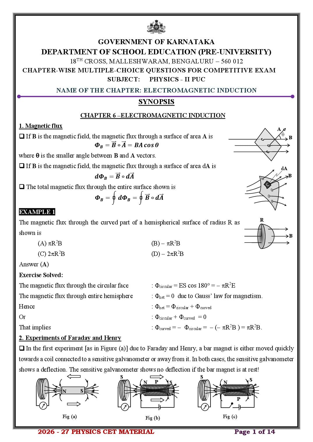
1. Magnetic flux A
❑ If B is the magnetic field, the magnetic flux through a surface of area A is
B
𝜱𝑩 = ⃗𝑩
⃗ ∘ ⃗𝑨 = 𝑩𝑨 𝒄𝒐𝒔 𝜽
where is the smaller angle between B and A vectors.
❑ If B is the magnetic field, the magnetic flux through a surface of area dA is dA
𝒅𝜱𝑩 = ⃗𝑩
⃗ ∘ 𝒅𝑨 ⃗ B
❑ The total magnetic flux through the entire surface shown is
𝜱𝑩 = ∮ 𝒅𝜱𝑩 = ∮ ⃗𝑩
⃗ ∘ 𝒅𝑨
⃗
EXAMPLE 1
R
The magnetic flux through the curved part of a hemispherical surface of radius R as
shown is B
(A) R2B (B) − R2B
(C) 2R2B (D) − 2R2B
Answer (A)
Exercise Solved:
The magnetic flux through the circular face : Φcircular = ES cos 180 = − R2E
The magnetic flux through entire hemisphere : Φnet = 0 due to Gauss’ law for magnetism.
Hence : Φnet = Φcircular + Φcurved
Or : Φcircular + Φcurved = 0
That implies : Φcurved = − Φcircular = − (− R2B ) = R2B.
2. Experiments of Faraday and Henry
❑ In the first experiment [as in Figure (a)] due to Faraday and Henry, a bar magnet is either moved quickly
towards a coil connected to a sensitive galvanometer or away from it. In both cases, the sensitive galvanometer
shows a deflection. The sensitive galvanometer shows no deflection if the bar magnet is at rest!
S S
P S
N S N
N S
P
Fig (a) Fig (b) Fig (c)
2026 - 27 PHYSICS CET MATERIAL Page 1 of 14
Page 2
moved quickly towards a secondary coil ‘S’ connected to a sensitive galvanometer or away from it. In both
cases, the sensitive galvanometer shows a deflection. The sensitive galvanometer shows no deflection if the
coil P is at rest!
❑ In the third experiment [as in Figure (c)], a current carrying coil ‘P’ is quickly switched ON and switched
OFF. The secondary coil ‘S’ is connected to a sensitive galvanometer which is near P. In both cases, the
sensitive galvanometer shows a deflection. The sensitive galvanometer shows no deflection if the switch of
the coil P is kept continually ON!
EXAMPLE 2
In the figure, the coil is connected to a sensitive galvanometer. The coil is free to
rotate about a horizontal axis as shown. When the coil is approaching the magnetic
N S
field of the bar magnet, the reading of the galvanometer is
(A) greater than that when it is at rest (B) less than when it is at rest.
(C) equal to that when the coil was at rest (D) greater than when the coil exits the field of the magnet
Answer (A)
3. Faraday’s Law and Lenz’s Law
❑ Faraday’s Law: The emf induced in a coil of N turns is directly proportional to the rate of change of
𝒅𝜱 𝒅
magnetic flux linked with it. That is ⃗⃗ ∘ 𝒅𝑨
𝑬 = −𝑵 𝒅𝒕𝑩 = 𝑵 𝒅𝒕 ∮ 𝑩 ⃗
Where B is the magnetic flux linked with the coil.
❑ Lenz’s Law: The polarity of induced emf is such that it tends to produce a current which opposes the
change in magnetic flux that produced it.
N S N S
❑ From the figure above, we find that as the bar magnet is moved towards the coil, the coil behaves as if it is
a north pole and when the magnet is moved away from it, it behaves as a south pole in accordance with the
Lenz’s law.
EXAMPLE 3
A certain elastic conducting material is stretched into a circular loop of 3 cm radius. It is placed with its plane
perpendicular to a uniform 0.8 T magnetic field. When released, the radius of the loop starts to shrink at an
instantaneous rate of 75 cm/s. The emf induced in the loop at that instant is nearly
(A) 0 (B) 3.5 mV (C) 7 mV (D) 1.3 mV
𝑑𝛷 𝑑𝐴 𝑑(𝜋𝑟 2 ) 𝑑𝑟
The induced emf in the loop is : |𝐸| = 𝑑𝑡𝐵 = 𝐵 𝑑𝑡 = 𝐵 = 2𝜋𝑟𝐵 𝑑𝑡
𝑑𝑡
𝑑𝑟
That is : |𝐸| = 2𝑟𝐵 = 2𝜋(3𝜋 × 10−2 )(0.8)(75 × 10−2 ) = 0.035𝑉 ≈ 3.5𝑚𝑉
𝑑𝑡
2026 - 27 PHYSICS CET MATERIAL Page 2 of 14
Page 3
If the circular conductor in the figure undergoes thermal expansion while it is in a uniform magnetic field, a
current is induced clockwise around it. The external magnetic field is
(A) directed into the page (B) directed out of the page
(C) directed into the page for some time and out of the page for the rest of the time
(D) proportional to the temperature of the conductor.
Answer (A)
Example Solved:
When the conductor expands, the magnetic flux linked with it increases. Hence it should produce a (induced)
magnetic field out of the plane of the page. That is the induced field must be opposite to the applied field.
Hence the applied field must be into the plane of the page.
4. Motional Emf
❑ When a conducting rod of length l is moved perpendicular to the external magnetic field
B with speed v normal to B, the emf induced across its ends is called motional emf which is l v
given by 𝑬 = 𝑩𝒍𝒗. B
❑ The mechanical power required to push the rod at the constant velocity v in the field is given by
𝑩𝟐 𝒍𝟐 𝒗𝟐
𝑷𝒎𝒆𝒄𝒉 = where R is the resis tan c e of the rod
𝑹
❑ The electrical power generated during the production of the motional emf is given by
𝑩𝟐 𝒍𝟐 𝒗𝟐
𝑷𝒆𝒍𝒆𝒄 =
𝑹
❑ The induced charge across the rod in the case of motional emf when the magnetic flux changes by B is
𝚫𝜱𝑩
𝚫𝑸 = where R is the resistance of the rod.
𝑹
EXAMPLE 5 I
A coil of resistance 20 is experiencing a change of flux. The variation of induced (A)
6
current vs time is shown in the graph. The magnitude of change of flux through the
coil (in Weber) is
t
(A) 2 (B) 4 (C) 8 (D) 12 0.2
(s)
Answer (D)
Example Solved:
The charge induced
𝛥𝛷𝐵 1
: 𝛥𝑄 = = ∫ 𝐼𝑑𝑡 = area under 𝐼 − 𝑡 graph = 2 𝑏𝑎𝑠𝑒 × ℎ𝑒𝑖𝑔ℎ𝑡 ⇒ Δ𝛷𝐵 = 𝐴𝑟𝑒𝑎 × 𝑅
𝑅
1
That is : B = ⏟ × 6 × 0.2 × 20 = 12 Wb
2
𝑎𝑟𝑒𝑎
5. Self Inductance and Mutual Inductance
❑ The emf induced in the coil due to the change in the current and
l S
hence the change in the magnetic flux linked with it is given by
r r2
𝒅𝑰 P r1
𝑬 = −𝑳 𝒅𝒕
𝑑𝐼
where 𝑑𝑡 is the rate of change of current through the coil and L is
called the self-inductance of the coil. Fig (a) Fig (b)
2026 - 27 PHYSICS CET MATERIAL Page 3 of 14
Page 4
by
𝝁𝒐 𝑵𝟐 𝝅𝒓𝟐
𝑳=
𝒍
𝑑𝐼𝑃
❑ The emf induced in the secondary coil when the current changes in the primary at the rate of is given
𝑑𝑡
𝒅𝑰
by 𝑬𝑺 = −𝑴 𝒅𝒕𝑷
Where M is called the mutual inductance between the two coaxial coils.
❑ The mutual inductance [see the figure (b)] between two coaxial coils having number of turns N 1 and N2
and whose inner coil has radius r1 is given by
𝝁𝒐 𝑵𝟏 𝑵𝟐 𝝅𝒓𝟐𝟏
𝑴= 𝒍𝟐
where l2 is the length of the shorter coil.
EXAMPLE 6
The current in a coil changes from 2 A to 4 A in 0.02 s resulting in an induced emf of 6 V. The coefficient of
self induction of the coil is
(A) 0.6 H (B) 60 mH (C) 0.06 mH (D) 0.6 mH
Answer (B)
Example Solved:
𝑑𝐼
Induced emf in a self inductance coil is : E = −𝐿 𝑑𝑡
|𝐸| 6
That is : 𝐿 = 𝑑𝐼/𝑑𝑡 = 2 = 0.06 H or 60 mH.
( )
0.02
6. Energy Stored in the Inductor
❑ When a current I is passed through an inductor having self inductance L, the energy stored in it is given by
𝟏
𝑼𝑩 = 𝟐 𝑳𝑰𝟐 .
❑ The energy density (the energy per unit volume stored inside the inductor) is give by
𝑼𝑩 𝑩𝟐
𝒖𝑩 = = where 𝐵 is the magnetic field inside the inductor
𝑽 𝟐𝝁𝒐
EXAMPLE 8
The variation of the energy stored in a given inductor with the current through its coil is correctly shown in
Answer (C)
U U U U
I I I I
(A) (B) (C) (D)
Example Solved:
1
The energy stored in the inductor is given by : 𝑈𝐵 = 2 𝐿𝐼 2 ⇔ ⏟= 𝐶𝑥 2
𝑦
𝐸𝑞 𝑜𝑓 𝑝𝑎𝑟𝑎𝑏𝑜𝑙𝑎
2026 - 27 PHYSICS CET MATERIAL Page 4 of 14
Page 5
❑ When an alternating generator having a coil of area A and N turns
is rotated at an angular velocity of in an external uniform electric
field B, the induced emf (induced voltage) across its ends is
𝑬 = 𝑵𝑨𝑩𝝎 𝒔𝒊𝒏 𝝎 𝒕 ⇔ 𝒗 = 𝑵𝑨𝑩𝝎 𝒔𝒊𝒏 𝝎 𝒕 Coil
Where NAB = vmax is called the amplitude of the induced Slip
Rings
alternating voltage.
❑ The quantity is also called the angular frequency which is related
to the frequency of alternating voltage by
𝜔 = 2𝜋𝜈
EXAMPLE 8
The nature of the magnetic field in the case of an alternating current generator is
(A) uniform both w.r.t time and space (B) uniform with space but varying with time.
(C) uniform with time but varying with space (D) variable with time and space.
Answer (A)
*************************************
2026 - 27 PHYSICS CET MATERIAL Page 5 of 14
Page 6
1. A hemispherical surface with radius R is placed in the uniform
⃗ is as shown in the figure. The magnetic flux
magnetic field 𝐵
through the hemispherical surface is
(A) zero (B) 𝜋𝐵𝑅 2
(C) 2𝜋𝐵𝑅 2 (D) 4𝜋𝐵𝑅 2
2. A solenoid is 0.5 m long, has cross-sectional area 0.25𝑚2 and is wound with 500 turns of wire that carry
a current of 1.2A. The magnetic flux through the solenoid is
(A) 0.1885 Wb (B) 27. 7 × 10⁻⁵ 𝑊𝑏
(C) 150.7 × 10⁻⁵ 𝑊𝑏 (D) 37.7 × 10⁻⁵ 𝑊𝑏
⃗ = 𝐵0 (𝑖̂ + 𝑗̂ + 𝑘̂). A square loop of side 𝑎 lies in a plane whose
3. A uniform magnetic field is given by 𝐵
1
unit normal vector is 𝑛̂ = (𝑖̂ + 𝑗̂ − 2𝑘̂). The magnetic flux through the loop is
√6
𝐵 𝑎2 2𝐵0 𝑎2 𝐵 𝑎2
(A) 0 (B) − (C) − 0 (D) zero
√6 √6 √2
⃗ = (2𝑥)𝑖̂ + (3𝑦)𝑗̂ + 4𝑘̂. A square of side 𝑎 lies in the 𝑥𝑦-plane with
4. The magnetic field in a region is 𝐵
one corner at the origin. The magnetic flux through the square is
(A) 4𝑎2 (B) 2𝑎2 (C)5𝑎2 (D) zero
5. A square of side L m lies in the xy-plane in a region, where the magnetic field is given by 𝐵 =
𝐵0 (2𝑖̂ + 3𝑗̂ + 4𝑘̂)𝑇, where 𝐵0 is constant. The magnitude of flux passing through the square (in Wb) is
(A) 2𝐵0 𝐿2 (B) 3𝐵0 𝐿2 (C) 4𝐵0 𝐿2 (D) √29𝐵0 𝐿2
𝑟2
6. A circular loop of radius 𝑅 lies in the 𝑥𝑦-plane. Magnetic field is 𝐵 = 𝐵0 (1 + 𝑅2) along the positive 𝑧-
direction. Magnetic flux through the loop is
3 5
(A) 2 𝜋𝐵0 𝑅 2 (B) 𝜋𝐵0 𝑅 2 (C) 2𝜋𝐵0 𝑅 2 (D) 4 𝜋𝐵0 𝑅 2
7. A cube of side 𝑎 is placed in a uniform magnetic field. The magnetic flux through one face is 10 Wb.
Which statement is necessarily true?
(A) Flux through the opposite face is −10 Wb.
(B) Net magnetic flux through the cube is 10 Wb.
(C) Flux through adjacent faces is zero.
(D) Flux through each face has equal magnitude.
8. A circular loop of area 𝐴is kept in a uniform magnetic field 𝐵. Initially, the plane of the loop is parallel to
the magnetic field. The loop is rotated through 60∘ about one of its diameters. The change in magnetic flux
is
𝐵𝐴 √3 3
(A) 𝐵𝐴 (B) 2 (C) 2 𝐵𝐴 (D) 2 𝐵𝐴
9. A rectangular loop has sides 6 cmand 8 cm. It is placed in a magnetic field of magnitude 5 T. The
maximum possible magnetic flux through the loop is
(A) 0.024 Wb (B) 0.12 Wb (C) 2.4 Wb (D) 24 Wb
10. A circular metallic sheet has outer radius 𝑅and inner radius 𝑅/2. A uniform magnetic field acts
perpendicular to its plane. Magnetic flux through the sheet is
3 1 1
(A) 𝜋𝑅 2 𝐵 (B) 4 𝜋𝑅 2 𝐵 (C) 2 𝜋𝑅 2 𝐵 (D) 4 𝜋𝑅 2 𝐵
2026 - 27 PHYSICS CET MATERIAL Page 6 of 14
Page 7
perpendicular to 𝐵to an orientation where its plane is parallel to 𝐵. The change in magnetic flux is
𝐵𝜋𝑟 2
(A) 𝐵𝜋𝑟 2 (B) 2𝐵𝜋𝑟 2 (C) Zero (D) 2
2 (𝜔𝑡).
12. Flux through a loop varies as Φ = Φ0 sin The Maximum induced emf is
𝜔Φ0
(A) 𝜔Φ0 (B) 2𝜔Φ0 (C) (D) Zero
2
13. The magnetic flux (in weber) in a closed circuit of resistance 10Ω varies with time t (in second) according
to the equation 𝐵 = 6 𝑡 2 − 5 𝑡 + 10. The magnitude of the induced current at t = 0.25 s is
(A) 1.2 A (B) 0.2 A (C) 0.6 A (D) 0.8 A
14. A circular loop of radius 𝑟and resistance 𝑅is placed in a magnetic field varying as 𝐵(𝑡) = 𝐵0 (1 + 𝛼𝑡).
The plane of the loop is perpendicular to the field. The instantaneous power dissipated in the loop is
𝜋2 𝑟 4 𝐵02 𝛼2 𝜋 2 𝑟 4 𝐵02 (1+𝛼𝑡)2 𝜋 2 𝑟 4 𝐵02 𝛼2 (1+𝛼𝑡)2
(A) (B) (C) (D) Zero
𝑅 𝑅 𝑅
15. The magnetic field is perpendicular to the plane of circular coil and it is
increasing with time. Which of the following is CORRECT?
(A) No current is induced
(B) Induced current flows in anticlockwise direction
(C) Induced current flows in clockwise direction
(D) Magnetic flux through the coil is constant.
16. A current carrying solenoid is approaching a
conducting loop as shown in the figure. The direction
of induced current as observed by an observer on the
other side of the loop will be
(A) anticlockwise
(B) clockwise
(C) Either clockwise or anticlockwise
(D) No current is induced
17. In the following figure the north pole of a magnet is moved away
from a thick conducting loop connected with a capacitor. Then
(A) plate a acquires positive charge
(B) plate b acquires positive charge
(C) both plates a and b acquire positive charge
(D) both plates a and b acquire negative charge
18. A positive charge moves along the line AB, which lies in the same plane as a
circular loop of conducting wires as shown in the diagram. Which of the
following is CORRECT?
(A) No current is induced
(B) Induced current flows in anticlockwise direction
(C) Induced current flows in clockwise direction
(D) Magnetic flux linking with the coil is constant.
2026 - 27 PHYSICS CET MATERIAL Page 7 of 14
Page 8
in B as shown, when A is moved towards B and stops when A stops
moving. The current in A is counter clockwise. B is kept stationary when
A moves. We can infer that
(A) there is a constant current in the clockwise direction in A
(B) there is a varying current in A
(C) there is no current in A
(D) there is a constant current in the counter clockwise direction in A
20. A metallic rod of length 𝑙moves with velocity 𝑣 perpendicular to a magnetic field 𝐵. If the rod is rotated
so that it moves parallel to the magnetic field, the induced emf becomes
(A) 𝐵𝑙𝑣 (B) 2𝐵𝑙𝑣 (C) 𝐵𝑙𝑣/2 (D) Zero
21. A rod moves perpendicular to its length and the magnetic field. If both its speed and length are doubled,
the induced emf becomes
(A) 2 times (B) 4 times (C) 8 times (D) Unchanged
22. A rod moving in a magnetic field develops an emf of 4 V. If the magnetic field is halved and velocity is
tripled, the new emf is
(A) 2 V (B) 4 V (C) 6 V (D) 12 V
23. In a coil of resistance 10 W, the induced current developed by changing
magnetic flux through it, is shown in figure as a function of time. The
magnitude of change in flux through the coil in weber is
(A) 8 (B) 2
(C) 6 (D) 4
24. The annular disc of copper, with inner radius a and outer radius b is rotating
about an axis passing through center and perpendicular to its plane with
uniform angular speed 𝜔. A uniform magnetic field B is along the axis of
rotation then, the emf induced between inner and the outer rim of the disc is
B𝜔𝑎2 B𝜔𝑏 2
(A) (B)
2 2
B𝜔(𝑏 2 −𝑎2 )
(C) (D) Zero
2
25. A conducting rod AB of length L is projected on a frictionless frame
PSRQ with velocity v at any instant. The velocity of the rod after
time t is
(A) increases (B) decreases
(C) remains same (D) becomes zero
26. The graph shows the magnitude 𝐵(𝑡)of a uniform magnetic field,
perpendicular to the plane of a conducting loop, as a function of time. In
which region is the magnitude of the induced emf maximum?
(A) I (B) II
(C) III (D) IV
2026 - 27 PHYSICS CET MATERIAL Page 8 of 14
Page 9
changes with time as shown in figure. The induced current in the loop at
t = 1s is
(A) 0.1 A (B) 0.2 A
(C) 0.4 A (D) 1 A
28. The magnetic flux through a coil varies with time t as shown in the diagram.
The correct representation of the variation of the emf E induced in the coil
with time t is
(A) (B)
(C) (D)
29. A short bar magnet passes at a constant speed right through a long
solenoid. A galvanometer G is connected across the solenoid. The
best representation of the variation of galvanometer deflection
with time t is
(A) (B)
(C) (D)
30. The current i in an induction coil varies with time t according to the graph shown
in figure. Which of the following graphs shows the induced emf (E) in the coil with
time?
(A) (B)
(C) (D)
2026 - 27 PHYSICS CET MATERIAL Page 9 of 14
Page 10
across a source of 10 V as shown in figure. The net emf of the circuit
when the current in an inductor changes at the rate 5 As-1 is
(A) 2𝑉 (B) −2𝑉 (C) 5𝑉 (D) −5𝑉
32. A coil has an inductance of 50 mH and a resistance of 2Ω are connected in series to battery if 10 V. The
magnetic energy is stored in an inductor if the current has built up to its maximum value is
(A) 0.625 J (B) 0.125 J (C) 0.250 J (D) zero
33. Two coils, A of 10000 turns and B of 15000 turns lie in parallel planes so that 50% of flux produced in
A links with B. It is found that a current of 5 A in A produces a flux of 0.6 mWb while the same current
in B produces 0.8 mWb. The mutual induction is
(A) 0.6 H (B) 0.8 H (C) 0.9 H (D) 1.2 H
34. In an inductor, the current I varies with time t as I = 5 + 20t. If induced emf in the inductor is 5 mV, the
self-inductance of the inductor is
(A) 0.25 mH (B) 0.5 mH (C) 4 mH (D) 5mH
35. A coil has inductance 5 𝐻and carries a current of 2 𝐴. The magnetic energy stored is
(A) 5 J (B) 10 J (C) 20 J (D) 40 J
36. If the inductance of a coil is doubled while current is halved, the stored magnetic energy becomes
(A) Half (B) Same (C) Double (D) One-fourth
37. The induced emf in an AC generator is zero when the plane of the coil is
(A) Parallel to the magnetic field (B) Perpendicular to the magnetic field
∘
(C) At 45 to the magnetic field (D) At 60∘ to the magnetic field
38. A generator coil rotates with angular speed 𝜔. If both the magnetic field and number of turns are
doubled, the maximum induced emf becomes
(A) Twice (B) Four times (C) Eight times (D) Sixteen times
39. Statement 1 : An induced emf appears in any coil in which the current is changing.
Statement 2 : Self induction phenomenon obeys Faraday's law of induction.
Choose the correct option
(A) Statement -1 is false, Statement-2 is true (B) Both Statements 1 and 2 are true
(C) Statement -1 is true, Statement-2 is false (D) Both Statements 1 and 2 are false
40. Consider the following:
List I List II
P. A conducting loop moves with constant velocity 1. Induced emf is maximum
completely inside a uniform magnetic field.
Q. A circular loop rotates with constant angular 2. No induced emf
velocity in a uniform magnetic field.
R. A straight conducting rod moves perpendicular 3. Motional emf = 𝐵𝑙𝑣
to its length as well as the magnetic field.
S. Current through a nearby coil is increased 4. Induced emf due to changing magnetic flux
uniformly with time. without mechanical motion
Choose the correct option.
(A) P–2, Q–1, R–3, S–4 (B) P–1, Q–2, R–4, S–3
(C) P–2, Q–4, R–1, S–3 (D) P–4, Q–3, R–2, S–1
2026 - 27 PHYSICS CET MATERIAL Page 10 of 14
Page 11
1 2 3 4 5 6 7 8 9 10
B A D A C A A C A B
11 12 13 14 15 16 17 18 19 20
A B B A C B A C D D
21 22 23 24 25 26 27 28 29 30
B C B C B C B C A D
31 32 33 34 35 36 37 38 39 40
C B A A B A B B B A
2026 - 27 PHYSICS CET MATERIAL Page 11 of 14
Page 12
1. A rod of length 2 m slides with a speed of 5 𝑚 𝑠 −1 on a rectangular
conducting frame as shown in figure. There exists a uniform magnetic
field of 0.04 T perpendicular to the plane of the figure. If the
resistance of the rod is 3Ω. The current through the rod is [2020]
(A) 133 mA (B) 0.75 A (C) 1.33 A (D) 75 mA
2. The current in a coil of inductance 0.2 H changes from 5 A to 2 A in 0.5 s. The magnitude of the average
induced emf in the coil is [KCET-2020]
(A) 1.2 V (B) 30 V (C) 0.3 V (D) 0.6 V
3. The current flowing through an inductance coil of self-inductance 6 mH at different
time instants is as shown. The emf induced between 𝑡 = 20 𝑠 and 𝑡 = 40 𝑠 is
nearly [KCET-2021]
−2 −4
(A) 2 × 10 𝑉 (B) 3 × 10 𝑉
(C) 4 × 10⁻³ 𝑉 (D) 30 × 102 𝑉
4. The physical quantity which is measured in the unit of 𝑊𝑏 𝐴−1 is [KCET-2021]
(A) self-inductance (B) mutual-inductance
(C) magnetic flux (D) both (A) and (B)
5. A long solenoid has 500 turns. When a current of 2 A is passed through it, the resulting magnetic flux linked
with each turn of the solenoid is 4 × 10⁻³ 𝑊𝑏 , then self-inductance of the solenoid is [KCET-2022]
(A) 2.0 henry (B) 1.0 henry (C) 4.0 henry (D) 2.5 henry
6. A magnetic field of flux density 1.0 𝑊𝑏 𝑚−2 acts normal to a 80 turn coil of 0.01 𝑚2 area. If this coil is
removed from the field in 0.2 second, the emf induced in it is [KCET-2022]
(A) 0.8 V (B) 5 V (C) 4 V (D) 8 V
7. The current in a coil changes from 2 A to 5 A in 0.3 s. The magnitude of emf induced in the coil is 1.0
V. The value of self-inductance of the coil is [KCET-2023]
(A) 100 mH (B) 0.1 mH (C) 10 mH (D) 1.0 mH
8. A metallic rod of length 1 m held along east-west direction is allowed to fall down freely. Given horizontal
component of earth’s magnetic field 𝐵𝐻 = 3 × 10⁻⁵ 𝑇. The emf induced in the rod at an instant 𝑡 = 2 𝑠
after it is released is (Take 𝑔 = 10 𝑚 𝑠 −2 ) [KCET-2023]
−3 −4 −3
(A) 3 × 10 𝑉 (B) 3 × 10 𝑉 (C) 6 × 10 𝑉 (D) 6 × 10⁻⁴ 𝑉
9. A square loop of side 2 cm enters a magnetic field with a constant speed of
2 𝑐𝑚 𝑠 −1 as shown. The front edge enters the field at 𝑡 = 0 𝑠. Which of the
following graph correctly depicts the induced emf in the loop? (Take
clockwise direction positive) [KCET-2023]
2026 - 27 PHYSICS CET MATERIAL Page 12 of 14
Page 13
downwards. These magnetic field lines pass through a closed surface as
shown in the figure. The closed surface consists of a hemisphere 𝑆1, a right
circular cone 𝑆2 . The circular surface is 𝑆3 . The magnetic flux through 𝑆1
and 𝑆2 are respectively (R = 10/√π cm) [KCET-2024]
(A) 𝜙𝑠1 = −20 𝜇𝑊𝑏 , 𝜙𝑠2 = +20 𝜇𝑊𝑏
(B) 𝜙𝑠1 = +20 𝜇𝑊𝑏 , 𝜙𝑠2 = −20 𝜇𝑊𝑏
(C) 𝜙𝑠1 = −40 𝜇𝑊𝑏 , 𝜙𝑠2 = +40 𝜇𝑊𝑏
(D) 𝜙𝑠1 = −40 𝜇𝑊𝑏 , 𝜙𝑠2 = +40 𝜇𝑊𝑏
11. In the figure, a conducting ring of certain resistance is falling towards a
current carrying straight long conductor. The ring and conductor are in the
same plane. Then the [KCET-2024]
(A) induced electric current is zero
(B) induced electric current is anticlockwise
(C) induced electric current is clockwise
(D) ring will come to rest
12. An induced current of 2 A flows through a coil. The resistance of the coil is 10 Ω. What is the change in
magnetic flux associated with the coil in 1 ms? [KCET-2024]
(A) 0.2 × 10⁻² 𝑊𝑏 (B) 2 × 10⁻² 𝑊𝑏 (C) 22 × 10−2 𝑊𝑏 (D) 0.22 × 10⁻² 𝑊𝑏
13. A square loop of side length ‘a’ is moving away from an infinitely long current
carrying conductor at a constant speed ‘v’ as shown. Let ‘x’ be the instantaneous
distance between the long conductor and side AB. The mutual inductance (M) of
the square loop-long conductor pair changes with time (t) according to which of the
following graph? [KCET-2024]
14. When a bar magnet is pushed towards the coil, along its axis, as shown in the
figure, the galvanometer pointer deflects towards X. When this magnet is pulled
away from the coil, the galvanometer pointer [KCET-2025]
(A) deflects towards X (B) deflects towards X'
(C) does not deflect (D) oscillates
⃗ = (2𝑖̂ + 3𝑗̂ − 4𝑘̂ ) 𝑇.
15. A square loop of side 2 m lies in the Y-Z plane in a region having magnetic field 𝐵
The magnitude of magnetic flux through the square loop is [KCET-2025]
(A) 10 Wb (B) 20 Wb (C) 12 Wb (D) 16 Wb
2026 - 27 PHYSICS CET MATERIAL Page 13 of 14
Page 14
galvanometer, which of the following statement/s is/are WRONG? [KCET-2026]
The pointer in the galvanometer deflects,
(a) When the bar magnet is moved towards the stationary coil along its axis
(b) When the bar magnet is moved away from the stationary coil along its axis
(c) When the coil is moved towards the stationary bar magnet along its axis
(d) When the coil and bar magnet are moved without the relative motion between them
(A) a and b (B) b and c (C) a, b and c (D) only d
17. In the figure shown, the conductor PQ of length l is moved from 𝑥 = 0 to 𝑥 = 𝑏 and then upto 𝑥 = 2𝑏
with a constant velocity 𝑣. A uniform magnetic field 𝐵⃗ is perpendicular to the plane of the paper and
extends from 𝑥 = 0 to 𝑥 = 𝑏 and it is zero from 𝑥 > 𝑏. The magnitude of emf induced in the conductor is
[KCET-
2026]
(A) 𝐵𝑙𝑥 ; 0 ≤ 𝑥 < 𝑏
(B) 𝑧𝑒𝑟𝑜 ; 0 ≤ 𝑥 < 𝑏
(C) 𝐵𝑙𝑣 ; 0 ≤ 𝑥 ≤ 𝑏
(D) 𝐵𝑙𝑣 ; 𝑏 ≤ 𝑥 < 2𝑏
KEY ANSWERS
1 2 3 4 5 6 7 8 9
A A B D B C A D C
10 11 12 13 14 15 16 17
A C B A B B D C
2026 - 27 PHYSICS CET MATERIAL Page 14 of 14
Document Details
| Board / Org | Karnataka Board |
| Exam | Class 12 |
| Type | Question Bank |
| Pages | 14 |
| Updated | 24 Sep 2026 |