ISC Class 12 Question Paper 2020 for Physics Practical
Finished viewing? Save it for later —
Download ISC Class 12 Question Paper 2020 for Physics Practical (PDF · 3 pages)About ISC Class 12 Question Paper 2020 for Physics Practical
ISC Class 12 Question Paper 2020 for Physics Practical is available here for free download. Published by CISCE for Class 12, this question paper can be viewed online or downloaded as a PDF (3 pages). Candidates preparing for Class 12 can use ISC Class 12 Question Paper 2020 for Physics Practical to understand the exam pattern, the type of questions asked, and the overall difficulty level.
Frequently Asked Questions
How can I download ISC Class 12 Question Paper 2020 for Physics Practical?
Open this page and click the Download button to save ISC Class 12 Question Paper 2020 for Physics Practical as a PDF. It is completely free on AglaSem Docs.
Is ISC Class 12 Question Paper 2020 for Physics Practical free to download?
Yes. ISC Class 12 Question Paper 2020 for Physics Practical can be viewed online and downloaded as a PDF free of cost on AglaSem Docs.
How many pages does ISC Class 12 Question Paper 2020 for Physics Practical have?
ISC Class 12 Question Paper 2020 for Physics Practical contains 3 pages, which you can read online or download together as a single PDF.
Where can I find more Class 12 study material?
You can find more Class 12 question papers, sample papers, syllabus, and answer keys on AglaSem Docs.
ISC Class 12 Question Paper 2020 for Physics Practical – Text
Read the full text of this question paper below — useful to quickly search, copy and reference the content online without downloading the PDF.
📄 View text version (3 pages)
Page 1
PAPER – 2
(PRACTICAL)
(Maximum Marks: 30)
(Time allowed: Three hours)
(Candidates are allowed additional 15 minutes for only reading the paper.
They must NOT start writing during this time.)
ALL ANSWERS MUST BE WRITTEN IN THE ANSWER BOOKLET
PROVIDED SEPARATELY.
If squared paper is used, it must be attached to the answer booklet.
Marks are given for a clear record of observations actually made, for their suitability
and accuracy, and for the use made of them.
Statement of the theory, procedure of the experiment, apparatus, circuit diagrams,
precautions are not required to be written unless specifically asked for.
Candidates are advised to record their observations as soon as they have been made.
All working, including rough work, should be done on the same sheet as, and adjacent to, the
rest of the answer.
Mathematical tables and squared paper are provided. The intended marks for questions
or parts of questions are given in brackets [ ].
Note: Procedure of the Experiment, ray diagram, circuit diagram and precautions are not to
be written in your answer booklet.
Answer all questions.
You should not spend more than one and a half hours on each question.
Question 1 [9]
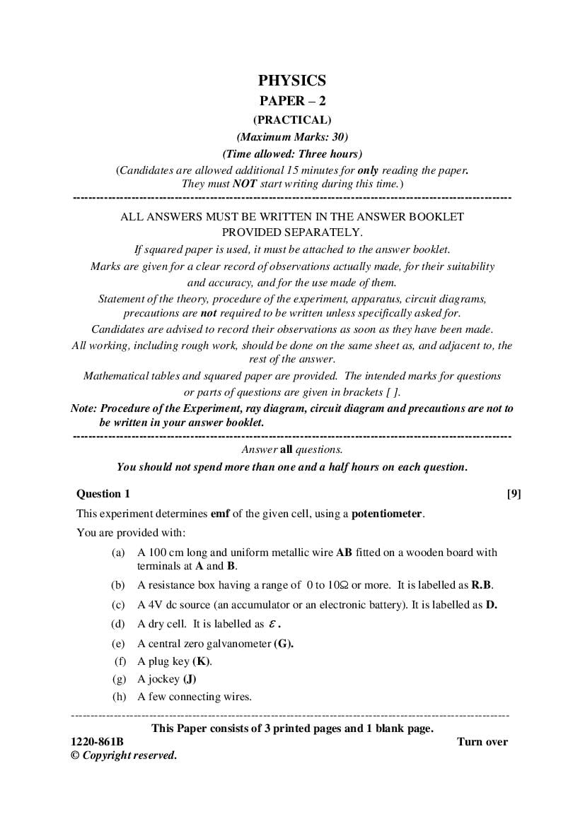
This experiment determines emf of the given cell, using a potentiometer.
(a) A 100 cm long and uniform metallic wire AB fitted on a wooden board with
terminals at A and B.
(b) A resistance box having a range of 0 to 10Ω or more. It is labelled as R.B.
(c) A 4V dc source (an accumulator or an electronic battery). It is labelled as D.
(d) A dry cell. It is labelled as .
(e) A central zero galvanometer (G).
(f) A plug key (K).
(g) A jockey (J)
(h) A few connecting wires.
This Paper consists of 3 printed pages and 1 blank page.
1220-861B Turn over
© Copyright reserved.
Page 2
D K
R.B. (• ) •
l B
A• P •
0 cm J 100 cm
G
Figure 1
Ensure that all connections are tight.
(ii) Keep the value of D at 4 V.
(iii) Close the key K. Remove 2Ω plug from the resistance box so that R = 2Ω.
(iv) Now, gently touch the jockey J on the wire AB and locate the balance point P, such
that the galvanometer shows no deflection. Ensure that all other plugs in the
resistance box are kept tightly closed.
Note and record the balancing length AP = l cm, correct up to one decimal place.
(v) Repeat the experiment for five more values of R such that R = 3Ω, 4Ω, 5Ω, 6Ω and
7Ω. Each time, find the balance point and obtain the balancing length l.
(vi) Tabulate all six sets of values of l and R with their units.
(vii) Show any one of the readings in (vi) to the Visiting Examiner.
(viii) Plot a graph of l vs R, taking l on y axis and R on x axis.
Draw the line of best fit.
(ix) From the graph, find 𝒍𝟎 , the value of l when R= 0.
(x) Calculate the value of using:
𝒍
= 𝟐𝟓𝟎
and record its value with proper unit, correct up to two decimal places.
Question 2 [6]
This experiment determines the focal length of the given convex lens by no parallax
method.
(a) An optical bench
(b) A lens holder
(c) A convex lens
(d) Two optical pins
Note: If an optical bench is not available, the experiment may be performed
on a table top, using a metre scale.
2
Page 3
table top as shown in Figure 2 below. Adjust the heights of the object pin O and the
image pin I so that the tips of O and I lie on the principal axis of the lens.
Iʹ
O L I
0 cm 100 cm
u v
Figure 2
(ii) Place the object pin O at the 0 cm mark and the lens L at the 30·0 cm mark, so that
the object distance u = 30·0 cm (i.e. the distance between the lens and the object pin).
(iii) Look at the tip of the object pin O through the lens from a distance so that you see
an inverted image (say Iʹ) of the object pin.
(iv) Now, adjust the position of the image pin I in such a way, that there is no parallax
between I and Iʹ. Ensure that tip to tip parallax is removed.
(v) At no parallax, note the position of the image pin I and measure the image distance
v = LI (i.e. the distance between the lens and the image pin) in cm, correct up to
one decimal place.
(vi) Repeat the experiment for four more values of u, i.e. u =40·0 cm, 50·0 cm, 60·0 cm
and 70·0 cm.
𝑣
(vii) For each value of u, calculate m = v/u and f = 𝑚+1 up to three significant figures.
(viii) Tabulate all five sets of u, v, m and f with their units (if any).
(ix) Show the image position when the parallax has been removed, in any one of the
readings in (viii) above, to the Visiting Examiner.
(x) Find F, the average of all the five values of f from the observation table and record
its value with proper units. Write your answer up to one decimal place.
Question 3
Show the following to the Visiting Examiner for assessment:
Project [10]
Physics Practical File. [5]
3
Document Details
| Board / Org | CISCE |
| Exam | Class 12 |
| Type | Question Paper |
| Pages | 3 |
| Language | english |
| Updated | 22 Jul 2026 |