PU CET PG 2018 Question Paper M.E. Electrical Engg. _Instrumentation _ Control_
Finished viewing? Save it for later —
Download PU CET PG 2018 Question Paper M.E. Electrical Engg. _Instrumentation _ Control_ (PDF · 8 pages)About PU CET PG 2018 Question Paper M.E. Electrical Engg. _Instrumentation _ Control_
PU CET PG 2018 Question Paper M.E. Electrical Engg. _Instrumentation _ Control_ is available here for free download. Published by Punjab University for PU CET PG, this question paper can be viewed online or downloaded as a PDF (8 pages). Candidates preparing for PU CET PG can use PU CET PG 2018 Question Paper M.E. Electrical Engg. _Instrumentation _ Control_ to understand the exam pattern, the type of questions asked, and the overall difficulty level.
Frequently Asked Questions
How can I download PU CET PG 2018 Question Paper M.E. Electrical Engg. _Instrumentation _ Control_?
Open this page and click the Download button to save PU CET PG 2018 Question Paper M.E. Electrical Engg. _Instrumentation _ Control_ as a PDF. It is completely free on AglaSem Docs.
Is PU CET PG 2018 Question Paper M.E. Electrical Engg. _Instrumentation _ Control_ free to download?
Yes. PU CET PG 2018 Question Paper M.E. Electrical Engg. _Instrumentation _ Control_ can be viewed online and downloaded as a PDF free of cost on AglaSem Docs.
How many pages does PU CET PG 2018 Question Paper M.E. Electrical Engg. _Instrumentation _ Control_ have?
PU CET PG 2018 Question Paper M.E. Electrical Engg. _Instrumentation _ Control_ contains 8 pages, which you can read online or download together as a single PDF.
Where can I find more PU CET PG study material?
You can find more PU CET PG question papers, sample papers, syllabus, and answer keys on AglaSem Docs.
PU CET PG 2018 Question Paper M.E. Electrical Engg. _Instrumentation _ Control_ – Text
Read the full text of this question paper below — useful to quickly search, copy and reference the content online without downloading the PDF.
📄 View text version (8 pages)
Page 1
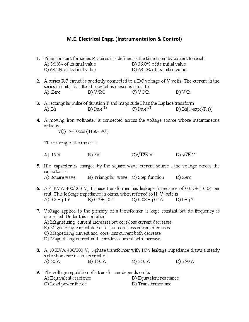
1. Time constant for series RL circuit is defined as the time taken by current to reach
A) 36.8% of its final value B) 36.8% of its initial value
C) 63.2% of its final value D) 63.2% of its initial value
2. A series RC circuit is suddenly connected to a DC voltage of V volts. The current in the
series circuit, just after the switch is closed is equal to
A) Zero B) V/RC C) VC/R D) V/R
3. A rectangular pulse of duration T and magnitude I has the Laplace transform
A) I/s B) I/s.e-T.s C) I/s.e-s/T D) I/s[1-exp(-T.s)]
4. A moving iron voltmeter is connected across the voltage source whose instantaneous
value is
v(t)=5+10cos (413t+ 300)
The reading of the meter is
A) 15 V B) 5V C)√125 V D) √75 V
5. If a capacitor is charged by the square wave current source , the voltage across the
capacitor is
A) Square wave B) Triangular wave C) Step function D) Zero
6. A 4 KVA 400/200 V, 1-phase transformer has leakage impedance of 0.02 + j 0.04 per
unit. This leakage impedance in ohms, when referred to H. V. side is
A) 0.8 + j 1.6 B) 0.2 + j 0.4 C) 0.08 + j 0.16 D)1 + j 2
7. Voltage applied to the primary of a transformer is kept constant but its frequency is
decreased. Under this condition
A) Magnetizing current increases but core-loss current decreases
B) Magnetising current decreases but core-loss current increases
C) Magnetising current and core-loss current both decrease
D) Magnetising current and core-loss current both increase
8. A 10 KVA 400/200 V, 1-phase transformer with 10% leakage impedance draws a steady
state short-circuit line current of
A) 50 A B) 150 A C) 250 A D) 350 A
9. The voltage regulation of a transformer depends on its
A) Equivalent reactance B) Equivalent reactance
C) Load power factor D) Transformer size
Page 2
secondary windings respectively. This transformer has
A) HV primary B) Medium voltage primary
C) LV primary D) LV secondary
11. A winding of 20 full pitch series turns, distributed over a band of 600under each pole ,
carries a current of 3 A. The winding produces a uniform current sheet of density ( in
ATs per electrical rad) of
A) 180/п B) 120/п C) 90/п D) 60/п
12. A sinusoidal current sheet in a rotating electrical machine has peak value along q-axis.
The peak value of sinusoidal mmf would be
A) In phase with peak current
B) 900 lagging the peak current
C) 900 leading the peak current
D) May lag or lead depending upon the type of machine
13. The fifth harmonic mmfwave, produced by 3-phase currents flowing in 3-phase balanced
winding, rotates w.r.t. the fundamental field(N s=speed of fundamental mmf wave) at a
speed of
A) 6/7.Ns B) 7/6.Ns C) 8/7.Ns D)7/8.Ns
14. A DC shunt motor is running at 1200 rpm when excited with 220V DC. Neglecting the
losses and saturation, the speed of the motor when connected to a 175 V DC supply is
A) 750 rpm B) 900 rpm C) 1050rpm D) 1200rpm
15. A DC series motor drawing an armature current of Ia is operating under saturated
magnetic conditions. The torque developed in the motor is proportional to
A) 1/Ia B) 1/Ia2 C) Ia2 D) Ia
16. Three point starter for DC shunt motor is not used where wide speed control above rated
speed is required because
A) The motor may stop at high speed
B) The motor may stop at low speed
C) Hunting may occur in the motor
D) Motor may attain dangerously high speed
17. A 200 V DC shunt motor delivers an output of 17 KW. The field winding resistance is 50
ohms and the armature-field resistance is 0.04 ohms. Maximum efficiency will be
obtained when total armature ohmic losses are equal to
A) 2632 W B) 3000 W C) 3680 W D) 5232 W
18. A 3-phase cylindrical rotor synchronous generator, with its armature resistance and
leakage reactance being neglected, is synchronized to an infinite bus and its field is kept
constant thereafter. Now the machine is loaded by supplying mechanical input to the
Page 3
would be
A) 0.866 leading B) 0.866 lagging C) 0.5 leading D) 0.5 lagging
19. A synchronous motor with negligible armature resistance runs at a load angle of 20 0 at
rated frequency. If the supply frequency is increased by 10% , keeping other parameters
constant , the new load angle will be
A) 160 B) 180 C) 200 D) 220
20. A non-salient type of three-phase , 50 Hz, 415 V4-pole synchronous motor on rated full
load draws rated line current at 0.9 pf lead. Under these conditions, the ratio of pull-out
torque to the developed torque on full-load is 2,5. The measurable torque angle will be
A) 23.560 B) 200 C) 300 D) 25.840
21. A cylindrical rotor type synchronous machine is delivering a constant load. When its
excitation is varied(δ=load angle, Ө= pf angle and armature resistance is zero), then
A) E f sinӨ = constant and Ia sin Ө= constant
B) E f cosӨ = constant and Ia cos Ө= constant
C) E f cosӨ = constant and Ia sin Ө= constant
D) E f sinӨ = constant and Ia cos Ө= constant
22. In a salient pole synchronous machine, load angle δ can be obtained from knowledge of
[Ө= pf angle and ra=0]
A) Vt, Ia,Xd,Ө B) Vt, Ia,Xd,Ө C) Vt, Ia,Xd,Xq,Ө D) Ef, Ia,Xq,Ө
23. The no-load speed of a 3-phase , 50 Hz IM is 1485 rpm. The number of alterations per
minute which the rotor emf will make and the speed of rotor mmfwrt rotor would
respectively be
A) 0.5, 1485 rpm B) 30, zero rpm C) 15, 15 rpm D) 30, 15 rpm
24. A 3-phase, 50 Hz IM, takes a power in speed of 1440 rpm. Total stator losses are 1KW.
The slip and rotor ohmic losses at full load are
A) 0.02, 600 W B) 0.04, 580 W C) 0.04, 1160 W D) 0.04, 1200 W
25. As compared to DOL starting, a cage IM with star-delta starting shall have
A) More starting torque B) More starting current
C) Reduced starting current D) Smooth acceleration
26. A starting torque of 100 Nm is developed in a 3-phase SCIM by an auto transformer
starter with tapping 40%. If the tapping of the auto transformer is changed to 80%, then
the starting torque would be
A) 400 Nm B) 200 Nm C) 50 Nm D) 25 Nm
27. Common emitter current gain hFE of a BJT is
A) Dependent on collector current Ic
Page 4
C) Dependent on base-emitter voltage ,VBE
D) Aalways constant
28. High frequency operation of a circuit is limited by
A) On-state loss in the device B) Off-state loss in the device
C) Switching losses in the device D) All of the above
29. The centre-tap full-wave single phase rectifier circuit uses two diodes. The transformer
turns ratio from primary to each secondary is 2. In case transformer input voltage is 200
V at 50 Hz , then rms voltage across each diode is
A) 565.6 V B) 282.8 V C) 70.7V D) 141.4 V
30. A single-phase two-pulse diode bridge has input supply of 200 sin ωt with load R=50 Ω.
Rms voltage across each diode is
A) 100 V B) 141.4 V C) 200 V D) 200/ V
31. A 3-phase half-wave diode rectifier feeds a load of R=100Ω. For an input supply of 400
V, 50 Hz, the power delivered to load is
A) 753.73 W B) 974.23 W C) 376.98 W D) 487.26 W
32. In a thyristor, the ratio of holding current to latching current is
A) 0.4 B) 1.0 C) 2.5 D) 4.00
33. For normal SCRs, turn on time is
A) Less than turn-off time,tq B) More than tq
C) Equal to tq D) About half of tq
34. For series connected SCRs, dynamic equalizing circuit consists of
A) Resistor R and capacitor C in series but with a diode D across C
B) Series R and C circuit but with C across R
C) Series R and C circuit but with D across R
D) Series C and D circuit but with R across C
35. An UJT exhibits negative resistance region
A) Before the peak point B) Between peak and valley points
C) After the valley point D) Both A and C
36. TRIACs are most suitable when the supply voltage is
A) DC B) Low frequency ac
C) High frequency AC D) Full wave rectified ac
37. A series circuit consists of R=2.4 Ω, L= 25 µH and a thyristor. For obtaining self-
commutation in the circuit, the value of C should be equal to
A) 50 µF B) 30 µF C) 20 µF D) 10 µF
Page 5
β is less than ᴫ . For a firing angle α, the SCR and freewheeling diode would,
respectively, conduct for
A) β-α, 00 B) -α, -β C) α, β-α D) β-α, α
39. In a single phase semi converter, if output voltage has peak and average values of 325 V
and 133 V respectively, then the firing angle is
A) 400 B) 73.40 C) 800 D) 1400
40. In a 3- phase semi converter, for firing angle less than or equal to 600, freewheeling diode
conducts for
A) 300 B) 600 C) 900 D) Zero degree.
41. In a 1- phase full converter, the number of SCRs conducting during overlap is
A) 1 B) 2 C) 3 D) 4
42. In dc choppers, per unit ripple is maximum when duty cycle α is
A) 0.2 B) 0.5 C) 0.7 D) 0.9
43. A step-up chopper is fed from a 220 V dc source to deliver a load voltage of 660 V. If the
non-conduction time of the thyristor is 100µs, the required pulse width would be
A) 100 µs B) 200 µs C) 220 µs D) 660 µs
44. A chopper, in which current remains positive but voltage may be positive or negative, is
known as
A) Type-A B) Type-B C) Type-C D) Type-D
( )
45. The polarization of wave with electric field vector = ( + ) is
A) Linear B) Elliptical C) Left hand circular D)Right hand circular
46. For a short circuited coaxial transmission line, Z o= 35+ 49 Ω, γ= 1.4+ 5 and the length
of line is 0.4m, the input impedance of the line is
A) 82 + 39 Ω B) 41 + 78 Ω C) 68 + 46 Ω D) 34 + 23 Ω
47. Divergence (∇. ) at ( , , 0) when the vector field = ∅ + ∅ ∅+
2 , will be
A) B) - C) D) -
48. Q48. A system with characteristic equation
+2 + 11 + 18 + 18 = 0will have closed loop poles such that
A) All poles lies on the left half of the plane
Page 6
C) Two poles lies symmetrically on the imaginary axis of the s-plane
D) No pole lies on the imaginary axis of the s-plane
49. The characteristic equation of a feedback control system is
2 + +3 + 5 + 10 = 0
The number of roots in the right half of the s-plane is
A) Zero B) 1 C) 2 D) 3
50. A linear discrete time system has the characteristic equation
− 0.81 = 0
The system
A) Is stable
B) Is marginally stable
C) Is unstable
D) Stability cannot be assessed from the given information.
51. If the fault current is 2000 A, the relay setting is 50% and the CT ratio is 400/5, then the
plug setting multiplier will be
A) 25 A B) 15 A C) 50 A D) None of these
52. If the phase angle of the voltage coil of a directional relay is 50 0 the maximum torque
angle of the relay is
A) 1300 B) 1000 C) 250 D) None of these
53. The capacitor switching is easily done by
A) Air blast circuit breaker B) Oil C.B.
C) Vaccum C.B. D) Any one of these
54. A fault is more severe from the view point of RRRV if it is a
A) Short line fault B) Medium line fault C) Long line fault D) None of these
55. The typical values of SCR for modern alternators is
A) 1.5 B) 1.2 C) 1.0 D) 0.5
56. The impulse ratio of a rod gap is
A) Unity B) Between 1.2 to 1.5
C) Between 1.6 to 1.8 D) Between 2 to 2.2
57. For stability and economic reasons we operate the transmission line with power angle in
the range. If the phase angle of the voltage coil of a directional relay is 50 0 the maximum
torque angle of the relay is
A) 100 to 250 B) 300 to 450 C) 600 to 750 D) 650 to 800
Page 7
A) 35 KA B) 49 KA C) 70 KA D) 89 KA
59. Phase modifier is installed in case of
A) Short transmission lines B) Medium transmission lines
C) Long transmission lines D) For all length lines
60. The buchholz relay protects a transformer from
A) All types of internal faults B) A turn to turn fault
C) Winding to winding fault D) None of them
61. The leakage resistance of a 50 km long cable is 1MΩ. For a 100 km long cable it will be
A) 1MΩ B) 2MΩ C) 0.66MΩ D) None of these
62. The coefficient of reflection for current for an open ended line is
A) 1.0 B) 0.5 C) -1.0 D) Zero
63. The coefficient of reflection of voltage for n short circuited line is
A) 1.0 B) -1.0 C) 0 D) 2.0
64. The positive sequence component of voltage at the point of fault is zero when it is a
A) 3-phase fault B) L-L fault C) L-L-G fault D) L-G fault
65. The motor which can be used on both a.c. and d.c. is
A) Reluctance motor B) Induction motor
C) D.C. series motor D) None of these
66. An ammeter has a current range of 0-5 A, and its internal resistance is 0.2 Ω. In order to
change the range to 0-25 A, we need to add a resistance of
A) 0.8 Ω in series with the meter B) 1.0 Ω in series with the meter
C) 0.04 Ω in parallel with the meter D) 0.05 Ω in parallel with the meter
67. A current of -8 + 6√2sin( + 30) A is passed through 3 meters. Theyare a centre zero
PMMC meter, a true rms meter and a moving iron instrument . The respective readings
(in A) will be
A) 8, 6, 10 B) -8, 6, 8 C) -8,10, 10 D) -8,2,2
68. The Q-meter works on the principle of
A) Mutual inductance B) Self inductance
C) Series resonance D) Parallel resonance
69. A digital to analog converter with a full-scale output voltage of 3.5 V has a resolution
close to 14mV. Its bit size is
A) 4 B) 8 C) 16 D) 32
70. A DC ammeter has a resistance of 0.1 Ω and its current range is 0-100A. If the range is to
be extended to 0-500 A, then meter requires the following shunt resistance
Page 8
71. The 8085 assembly language instruction that stores the content of H and Lregisters into
the memory locations 2050H and 2051H, respectively is
A) SPHL 2050H B) SPHL 2051H C) SPLD 2050H D) STAX 2050H
72. A memory system has a total of 8 memory chips, each with 12 address lines and 4 data
lines. The total size of the memory system is
A) 16 kbytes B) 32 kbytes C) 48 kbytes D) 64 kbytes
73. An op-amp has an open-loop gain of 105 and an openloop under cut-off frequency of 10
Hz. If this op-amp is connected as an amplifier with closed-loop gain of 100, then the
new cut-off frequency is
A) 10 Hz B) 100 Hz C) 10 kHz D) 100 kHz
74. What is the required value of CE for the circuit to have a lower cut-off frequency of 10Hz
A) 0.159 mF B) 1.59 mF C) 5µF D) 10 µF
75. The complete set of only those logic gates designated as universal gates is
A) NOT,OR and AND gates B) XNOR, NOR and NAND gates
C) NOR and NAND gates D) XNOR, NOR and NAND gates
x-x-x
Document Details
| Board / Org | Panjab University |
| Exam | PU CET PG |
| Type | Question Paper |
| Pages | 8 |
| Updated | 30 Apr 2026 |