RTU 2016 Question Paper Semester IV Civil Engineering Strength of Materials II
Finished viewing? Save it for later —
Download RTU 2016 Question Paper Semester IV Civil Engineering Strength of Materials II (PDF · 7 pages)About RTU 2016 Question Paper Semester IV Civil Engineering Strength of Materials II
RTU 2016 Question Paper Semester IV Civil Engineering Strength of Materials II is available here for free download. Published by Default for Semester Exams, this question paper can be viewed online or downloaded as a PDF (7 pages). Candidates preparing for Semester Exams can use RTU 2016 Question Paper Semester IV Civil Engineering Strength of Materials II to understand the exam pattern, the type of questions asked, and the overall difficulty level.
Frequently Asked Questions
How can I download RTU 2016 Question Paper Semester IV Civil Engineering Strength of Materials II?
Open this page and click the Download button to save RTU 2016 Question Paper Semester IV Civil Engineering Strength of Materials II as a PDF. It is completely free on AglaSem Docs.
Is RTU 2016 Question Paper Semester IV Civil Engineering Strength of Materials II free to download?
Yes. RTU 2016 Question Paper Semester IV Civil Engineering Strength of Materials II can be viewed online and downloaded as a PDF free of cost on AglaSem Docs.
How many pages does RTU 2016 Question Paper Semester IV Civil Engineering Strength of Materials II have?
RTU 2016 Question Paper Semester IV Civil Engineering Strength of Materials II contains 7 pages, which you can read online or download together as a single PDF.
Where can I find more Semester Exams study material?
You can find more Semester Exams question papers, sample papers, syllabus, and answer keys on AglaSem Docs.
RTU 2016 Question Paper Semester IV Civil Engineering Strength of Materials II – Text
Read the full text of this question paper below — useful to quickly search, copy and reference the content online without downloading the PDF.
📄 View text version (7 pages)
Page 1
t-{
F{
t< (rr,rtX4"1i1*"-, rrr"-lO
$
EI
B. rech. rv-sem
- r;;'-''
\il o
"r,
o tlll',:ffi illt,,,k.;
Min. passing r*#?i;I:tH:li; ;:
Instru ctions to Candidates Min. passing Marks (Otd Back):
:_
24
Attempt any.five questions,
selecting one question
Questions carry equat marks. from each unit. A,
sr!r;:";;i";;;;;r*,
yl;;;':;::;essary' An1'; 4o7o vou 7",t ii,,t"s i"inory must be shown
be assumed and
units of quantities used/ carcurated
must be stated clearry.
use offorowing supporting
materiar is permitted during
examination.
(Mentioned in
form No.205 )
1. NIL
2. NIL
UNIT-I
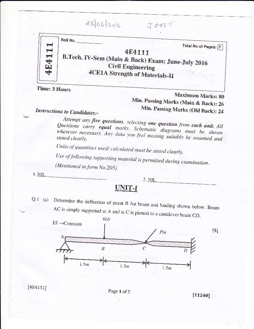
Q' l (a) Determine the deflection of point
B for beam and loading shown
AC is simply supported below. Beam
at A and at c is pinned
to a cantileu", u"r* cn.
8kN
EI -+Constant
t8l
[4841.1.11
Page I ofZ
11124ol
Page 2
end c. Flexural rigidity for beam AB is 3EI and for BC is EI.
t8l
*oh , 7t
3EI {Mo
,# nt)T
OR
as shown in fig
Q.l The cantilever beam AD is loaded by the applied couples M1 and M'6
at D' t16l
below. Determine the equation of the deflected beam & deflection
L L L
4 2 4
UNIT-II
of the
Q.2 For overhanging beam shown in fig. below.
Determine the magnitude
supporting force at B.
t16l
lOkN I m
C
l-agb +l
Page? of7 ltLz4ol
[4E4111]
Page 3
Q.2 (a) A propped cantilever is acted by a uniformly distributed moment of intensity m
per unit distance along the axis of the beam. Find the Reaction at B. t3l
J\,
(b) A masonry pier of 2m x 3m supports a vertical load of 50 kN as shown in fig
below. Find.
t8l
(i) Stresses developed at eacti corner of the pier.
(ii) What additional load should be placed at the centre of the pier, so that there
is no tension any where in the pier section
\l lv
A B
!
.
r.."0.8"- f T
x ... I ;0.4
-x 2m
I
-{.r-r
D C
lY
F-* 3m
-d
[4E41LL] Page 3 of7
11124ol
Page 4
at third points by two point loads
Q.3 Find the support moments of a built - in beam loaded
at the
W each. Also draw the B.M and S.F diagrams and compute the deflection
centre. t16l
'.)
k- ',+- ix i*t
OR
is simply supported at A' B
Q.3 A continuous beam ABC of constant moment of inertia
and c. The beam carries a central point load of 40 kN in span
AB and a central
clockwise couple of 300 kN-M in the Span BC. as shown in
fig. below' Find the
support moments and plot the shear force and bending moment
diagrams. t16l
a-
[4E4111]
Page 4 of7 ltLz4ol
Page 5
Q'4 (a) write down the assumptions used in developing the
equations for stresses and
deformation in a bar subjected to pure torsion.
141
(b) The stiffrress of a close-coiled helical spring is 1.5
N/mm of compression under a
maximum load of 60N' The maximum shearing
stress produced in the wire of the
tl** is 125 N/mm2' The solid length of the spring
t*rr", coils are touctring; is
grven as 5cm. Find
nzl
J (i) Diameter of wire
(ii) Mean diameter of the coils and
(iir) Number of coils required. Take N
= 4.5 x 10⁴ N/mm2 (Modulus of rigidity)
OR
Q'4 (a) Derive expressions for stiffness of composite springs
when two springs of
stiffrress 51 and 52 respectively are
arranged in
t6l
(i) Series &
(ii) Parallel
(b) Two shafts of the same material and of
same lengths are subjected to the same
torque, if the frst shaft is of a solid
circular section and the second shaft
is of
hollow circular section, whose internal
dia. is 213 of the outer dia. and max.
Shear stress developed in each shaft
is the same; compare the weights of the
shafu.
tl0l
148411.1l Page 5 of7
It124ol
Page 6
l4x4=l6f
(any four)
Q.5 Write short notes on the following
(a) Degrees of freedom'
(b) Consequences of vibration
of structures'
(c) Vibration control in the design
an SDoF'system
(d) Mathematical modelling of
(e) D' Alembert's PrinciPle
(0 TYPes of vibration'
OR
and a mass Mas
beam AB of Length
L is attached to a sPring K
Q.s (a) A cantilever t10l
shown in fig' below'
(i) Form the equation of motion'
'' of motion
(it) Find exPresstcrn for the frequencY
of spnng'
(iil) Determine static deflection
[112401
Page 6 of7
[4E41111
Page 7
the natural frequency of the
system.
t6l
[4E411L1 PageT of7
Itxz4ol
Document Details
| Board / Org | Default |
| Exam | Semester Exams |
| Type | Question Paper |
| Pages | 7 |
| Updated | 30 Apr 2026 |