ICSE Class 10 Question Paper 2019 for Technical Drawing Applications
Finished viewing? Save it for later —
Download ICSE Class 10 Question Paper 2019 for Technical Drawing Applications (PDF · 8 pages)About ICSE Class 10 Question Paper 2019 for Technical Drawing Applications
ICSE Class 10 Question Paper 2019 for Technical Drawing Applications is available here for free download. Published by CISCE for Class 10, this question paper can be viewed online or downloaded as a PDF (8 pages). Candidates preparing for Class 10 can use ICSE Class 10 Question Paper 2019 for Technical Drawing Applications to understand the exam pattern, the type of questions asked, and the overall difficulty level.
Frequently Asked Questions
How can I download ICSE Class 10 Question Paper 2019 for Technical Drawing Applications?
Open this page and click the Download button to save ICSE Class 10 Question Paper 2019 for Technical Drawing Applications as a PDF. It is completely free on AglaSem Docs.
Is ICSE Class 10 Question Paper 2019 for Technical Drawing Applications free to download?
Yes. ICSE Class 10 Question Paper 2019 for Technical Drawing Applications can be viewed online and downloaded as a PDF free of cost on AglaSem Docs.
How many pages does ICSE Class 10 Question Paper 2019 for Technical Drawing Applications have?
ICSE Class 10 Question Paper 2019 for Technical Drawing Applications contains 8 pages, which you can read online or download together as a single PDF.
Where can I find more Class 10 study material?
You can find more Class 10 question papers, sample papers, syllabus, and answer keys on AglaSem Docs.
ICSE Class 10 Question Paper 2019 for Technical Drawing Applications – Text
Read the full text of this question paper below — useful to quickly search, copy and reference the content online without downloading the PDF.
📄 View text version (8 pages)
Page 1
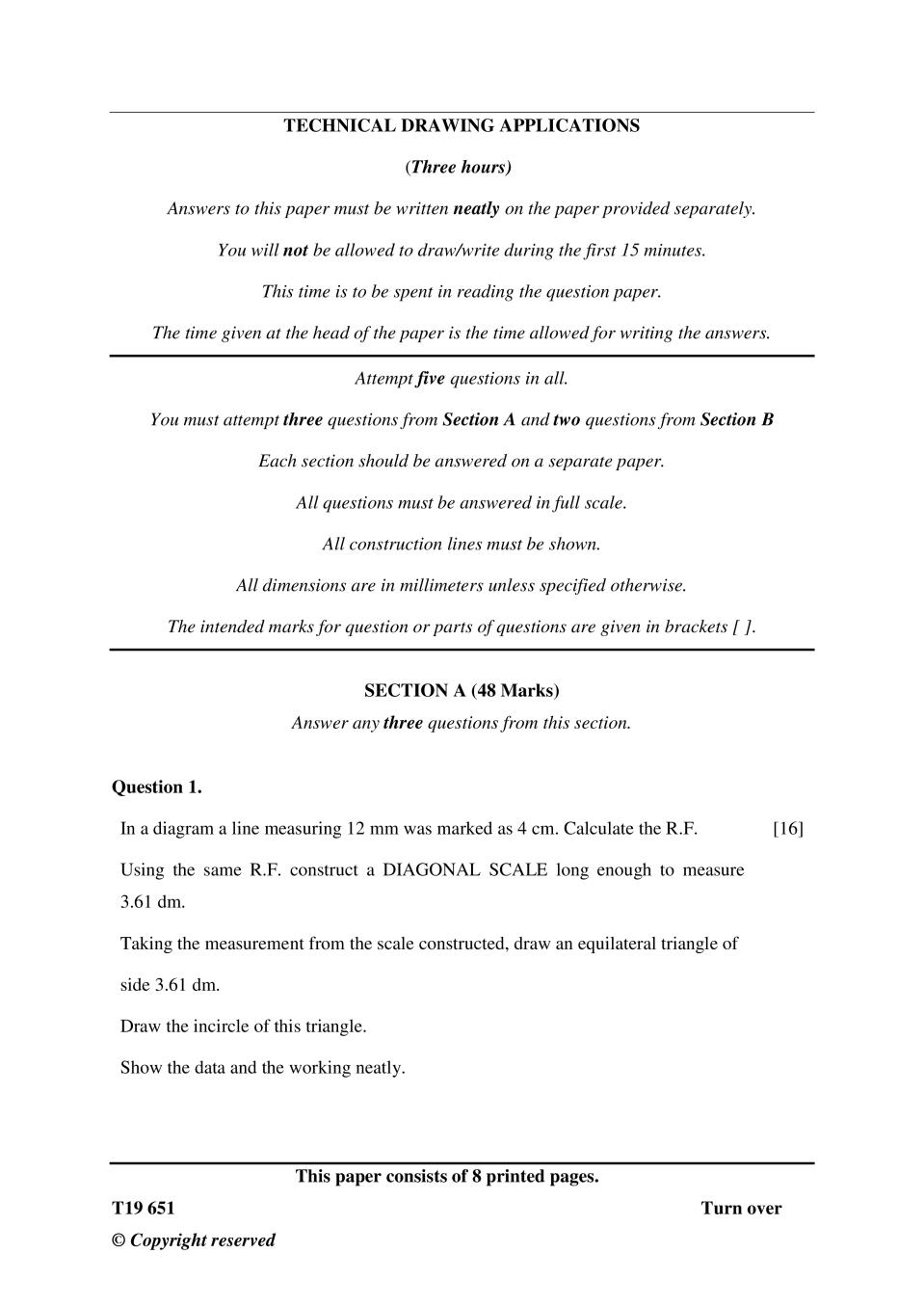
(Three hours)
Answers to this paper must be written neatly on the paper provided separately.
You will not be allowed to draw/write during the first 15 minutes.
This time is to be spent in reading the question paper.
The time given at the head of the paper is the time allowed for writing the answers.
Attempt five questions in all.
You must attempt three questions from Section A and two questions from Section B
Each section should be answered on a separate paper.
All questions must be answered in full scale.
All construction lines must be shown.
All dimensions are in millimeters unless specified otherwise.
The intended marks for question or parts of questions are given in brackets [ ].
SECTION A (48 Marks)
Answer any three questions from this section.
Question 1.
In a diagram a line measuring 12 mm was marked as 4 cm. Calculate the R.F. [16]
Using the same R.F. construct a DIAGONAL SCALE long enough to measure
3.61 dm.
Taking the measurement from the scale constructed, draw an equilateral triangle of
side 3.61 dm.
Draw the incircle of this triangle.
Show the data and the working neatly.
This paper consists of 8 printed pages.
T19 651 Turn over
© Copyright reserved
Page 2
Construct an ELLIPSE by the OBLONG METHOD. [16]
Given : Major Axis = 150 mm
Minor Axis = 100 mm.
Question 3.
(a) Draw a square of side 100 mm. Construct four equal circles inside the square [6]
so that each circle touches one side of the square and two other equal circles
externally.
(b) Refer to Figure 1 given below. It shows the Front View (F.V.) and the Top [10]
View (T.V.) of a right circular cylinder in the FIRST ANGLE METHOD of
projection. Its axis is perpendicular to the horizontal plane and parallel to the
vertical plane. Copy the given figure and draw its AUXILIARY TOP VIEW.
The auxiliary plane X1Y1 is shown in the figure.
Given: Diameter of the base = 70 mm
Length of axis = 75 mm.
Figure 1
T19 651 2
Page 3
Refer to Figure 2 given below. It shows the Front View (F.V.) and the Top View [16]
(T.V.) of an object in the FIRST ANGLE METHOD of projection. Draw the
OBLIQUE VIEW when the receding axis is inclined at 45° to the horizontal.
(Do not insert any dimensions.)
Figure 2
T19 651 3 Turn Over
Page 4
Refer to Figure 3 given below. Copy the given template. [16]
(Insert any 4 dimensions.)
Figure 3
T19 651 4
Page 5
Answer any two questions from this Section.
Question 6.
(a) Refer to Figure 4 given below. It shows the Front View (F.V.) and the Top [12]
View (T.V.) of a right hexagonal prism in the THIRD ANGLE METHOD of
projection.
Its axis is perpendicular to the horizontal plane (H.P.) and parallel to the
vertical plane (V.P.). Two sides of its base are perpendicular to the V.P. The
prism is cut by a cutting plane inclined at 60° to the H.P. and perpendicular to
the V.P. The Vertical Trace (V.T.) of the cutting plane is shown in the figure.
Draw the:
(i) Front View
(ii) Sectional Top View
(iii) Development of the Lateral Surface of the remaining part P of the Prism.
Given: Side of the base = 30 mm
Length of Axis = 70 mm.
Figure 4
T19 651 5 Turn Over
Page 6
View (T.V.) of a right square pyramid in the THIRD ANGLE METHOD of
projection.
Its axis is perpendicular to the horizontal plane (H.P.) and parallel to the
vertical plane (V.P.). The pyramid is cut by a cutting plane inclined at 30 ° to
the H.P. and perpendicular to the V.P. The Vertical Trace (V.T.) of the cutting
plane is shown in the figure. Draw the:
(i) Front View
(ii) Sectional Top View
(iii) Sectional Left Hand Side View
Given: Side of the base = 40 mm
Length of Axis = 75 mm.
Figure 5
T19 651 6
Page 7
Refer to Figure 6 given below. [26]
Copy the given ISOMETRIC VIEW.
(Do not insert any dimensions.)
Figure 6
T19 651 7 Turn Over
Page 8
Refer to Figure 7 given below. Using the FIRST ANGLE METHOD of projection, [26]
draw the:
(i) Full Sectional Front View [section along A - A]
(ii) Top View
(iii) Left Hand Side View.
(Insert any 6 dimensions.)
Figure 7
T19 651 8
Document Details
| Board / Org | CISCE |
| Exam | Class 10 |
| Type | Question Paper |
| Pages | 8 |
| Updated | 22 Jul 2026 |