CBSE Class 12 Physics Question Paper 2020 Set 55-4-2 Solutions
Finished viewing? Save it for later —
Download CBSE Class 12 Physics Question Paper 2020 Set 55-4-2 Solutions (PDF · 15 pages)About CBSE Class 12 Physics Question Paper 2020 Set 55-4-2 Solutions
CBSE Class 12 Physics Question Paper 2020 Set 55-4-2 Solutions is available here for free download. Published by CBSE for Class 12, this solution can be viewed online or downloaded as a PDF (15 pages). Candidates preparing for Class 12 can use CBSE Class 12 Physics Question Paper 2020 Set 55-4-2 Solutions to understand the exam pattern, the type of questions asked, and the overall difficulty level.
Frequently Asked Questions
How can I download CBSE Class 12 Physics Question Paper 2020 Set 55-4-2 Solutions?
Open this page and click the Download button to save CBSE Class 12 Physics Question Paper 2020 Set 55-4-2 Solutions as a PDF. It is completely free on AglaSem Docs.
Is CBSE Class 12 Physics Question Paper 2020 Set 55-4-2 Solutions free to download?
Yes. CBSE Class 12 Physics Question Paper 2020 Set 55-4-2 Solutions can be viewed online and downloaded as a PDF free of cost on AglaSem Docs.
How many pages does CBSE Class 12 Physics Question Paper 2020 Set 55-4-2 Solutions have?
CBSE Class 12 Physics Question Paper 2020 Set 55-4-2 Solutions contains 15 pages, which you can read online or download together as a single PDF.
Where can I find more Class 12 study material?
You can find more Class 12 question papers, sample papers, syllabus, and answer keys on AglaSem Docs.
CBSE Class 12 Physics Question Paper 2020 Set 55-4-2 Solutions – Text
Read the full text of this solution below — useful to quickly search, copy and reference the content online without downloading the PDF.
📄 View text version (15 pages)
Page 1
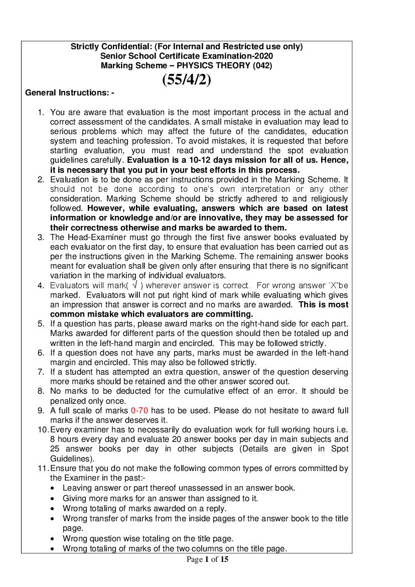
Senior School Certificate Examination-2020
Marking Scheme – PHYSICS THEORY (042)
(55/4/2)
General Instructions: -
1. You are aware that evaluation is the most important process in the actual and
correct assessment of the candidates. A small mistake in evaluation may lead to
serious problems which may affect the future of the candidates, education
system and teaching profession. To avoid mistakes, it is requested that before
starting evaluation, you must read and understand the spot evaluation
guidelines carefully. Evaluation is a 10-12 days mission for all of us. Hence,
it is necessary that you put in your best efforts in this process.
2. Evaluation is to be done as per instructions provided in the Marking Scheme. It
should not be done according to one’s own interpretation or any other
consideration. Marking Scheme should be strictly adhered to and religiously
followed. However, while evaluating, answers which are based on latest
information or knowledge and/or are innovative, they may be assessed for
their correctness otherwise and marks be awarded to them.
3. The Head-Examiner must go through the first five answer books evaluated by
each evaluator on the first day, to ensure that evaluation has been carried out as
per the instructions given in the Marking Scheme. The remaining answer books
meant for evaluation shall be given only after ensuring that there is no significant
variation in the marking of individual evaluators.
4. Evaluators will mark( √ ) wherever answer is correct. For wrong answer ‘X”be
marked. Evaluators will not put right kind of mark while evaluating which gives
an impression that answer is correct and no marks are awarded. This is most
common mistake which evaluators are committing.
5. If a question has parts, please award marks on the right-hand side for each part.
Marks awarded for different parts of the question should then be totaled up and
written in the left-hand margin and encircled. This may be followed strictly.
6. If a question does not have any parts, marks must be awarded in the left-hand
margin and encircled. This may also be followed strictly.
7. If a student has attempted an extra question, answer of the question deserving
more marks should be retained and the other answer scored out.
8. No marks to be deducted for the cumulative effect of an error. It should be
penalized only once.
9. A full scale of marks 0-70 has to be used. Please do not hesitate to award full
marks if the answer deserves it.
10. Every examiner has to necessarily do evaluation work for full working hours i.e.
8 hours every day and evaluate 20 answer books per day in main subjects and
25 answer books per day in other subjects (Details are given in Spot
Guidelines).
11. Ensure that you do not make the following common types of errors committed by
the Examiner in the past:-
Leaving answer or part thereof unassessed in an answer book.
Giving more marks for an answer than assigned to it.
Wrong totaling of marks awarded on a reply.
Wrong transfer of marks from the inside pages of the answer book to the title
page.
Wrong question wise totaling on the title page.
Wrong totaling of marks of the two columns on the title page.
Page 1 of 15
Page 2
Marks in words and figures not tallying.
Wrong transfer of marks from the answer book to online award list.
Answers marked as correct, but marks not awarded. (Ensure that the right
tick mark is correctly and clearly indicated. It should merely be a line. Same
is with the X for incorrect answer.)
Half or a part of answer marked correct and the rest as wrong, but no marks
awarded.
12. While evaluating the answer books if the answer is found to be totally incorrect,
it should be marked as cross (X) and awarded zero (0)Marks.
13. Any unassessed portion, non-carrying over of marks to the title page, or totaling
error detected by the candidate shall damage the prestige of all the personnel
engaged in the evaluation work as also of the Board. Hence, in order to uphold
the prestige of all concerned, it is again reiterated that the instructions be
followed meticulously and judiciously.
14. The Examiners should acquaint themselves with the guidelines given in the
Guidelines for spot Evaluation before starting the actual evaluation.
15. Every Examiner shall also ensure that all the answers are evaluated, marks
carried over to the title page, correctly totaled and written in figures and words.
16. The Board permits candidates to obtain photocopy of the Answer Book on
request in an RTI application and also separately as a part of the re-evaluation
process on payment of the processing charges.
Page 2 of 15
Page 3
QUESTION PAPER CODE: 55/4/2
Q.No. Value Points/Expected Answer Marks Total
Marks
SECTION A
1. (b) 𝑟 ∝ √𝑚 1 1
2. (b) Zero 1 1
3. (b) 1 1
4. ( c) 9 I 1 1
5. 𝑅 1 1
(c)
2
6. (b) 1× 10⁻⁵ T, acting upward 1 1
7. (b) 1:1 1 1
8. (a) Only on impact parameter 1 1
9. (c) π 1 1
10. (a) Infra red region 1 1
11. Anti neutrino 1 1
12. Pass axis/ optic axis 1 1
13. Decreasing/Lower 1 1
14. Middle/mid point /center 1 1
OR
Decrease
𝜋
15. 900 or 1 1
2
16. Reflecting type telescope 1 1
Reason/Justification :-
Mirror have large aperture/high resolving power/ free from
chromatic aberration /free from spherical aberration. ( Any one)
17. The displacement current will decrease. 1 1
𝑉 𝑉
𝐻𝑖𝑛𝑡 ∶ − (𝐼𝐶 = = 1 = ωCV) / the rate of change of electric
𝑋𝐶 (ωc)
flux/electric field will decrease
18. No ½ 1
As there will be discontinuity for the flow of charge carriers / no
contact at atomic level. ½
(Any One Justification)
OR
The forward current is large due to majority charge carriers which
are very large in number. Hence resistance in forward bias is low. 1
Alternatively: Depletion region decreases or barrier potential
decreases.
Page 3 of 15
Page 4
20. Angle subtended by the resultant magnetic field of earth with 1 1
respect to horizontal is called angle of dip.
SECTION B
21.
Finding initial resistance of wire 2
I net = I1 + I2 +I3 ½
𝐸 𝐸 𝐸
= + +
𝑅1 𝑅2 𝑅3
10 10 10
= + +
2𝑥 3𝑥 6𝑥
60 1
5= ; x=2
6𝑥
Therefore: 2
½
R=4 + 6 + 12=22 Ω
22.
(i) Finding average power dissipated 1
(ii) Finding instantaneous current 1
(i) Average power dissipated
𝑃1 = 𝐼𝑒𝑓𝑓 × 𝑉𝑒𝑓𝑓 × cos 00 ½
2 𝑉0 2
= 𝐼𝑒𝑓𝑓 × 𝐼𝑒𝑓𝑓 × 𝑅 × 1 = 𝐼𝑒𝑓𝑓 𝑅= ½
𝑅
(ii) Instantaneous Current
𝑉 𝑉 ½+ ½ 2
𝐼= = 0 sin 𝜔𝑡 = 𝐼0 sin 𝜔𝑡
𝑅 𝑅
23.
a) Calculating net capacitance
b) Calculating charge
1 1 1 ½
= +
𝐶𝑛𝑒𝑡 6+12 6+12
1 1 1
= + = ½
18 18
9
C net = 9µF
Q=CnetV ½
Q = 9×3 =27 µC ½ 2
Page 4 of 15
Page 5
(a) Energy bands in solids 1
(b) Drawing energy band diagram
(i) Metal ; (ii) Semiconductor ½+½
(a) Note: Out of syllabus; marks are distributed in part(b)
(b) [A student may draw both or any one]
(i)
1
(ii)
1 2
25
(a) Photo diode in reverse biasing 1
(b) V-I Characteristics of photodiode 1
(a) Because the fractional change in the minority carriers
dominated very weak reverse current is more easily 1
measurable than fractional change in forward biased large
current
(b)
1 2
I1>I2
OR
(a) Level of doping and biasing in LED 1
(b) Any two advantages of LED 1
(a) It is a heavily doped p-n junction.
It operates in forward biasing ½
(b) Advantages ½
Low operational voltage/less power /fast action / nearly
monochromatic / long life ( Any two) ½+½
2
Page 5 of 15
Page 6
Explanation of set up of potential barrier 2
Diffusion current is set up across the junction due to the
concentration difference of the majority charge carriers on the two 1
sides of the junction.
This diffusion develops an electric field from n- side to p- side ½
across the junction which creates a drift current in the opposite
direction.
When diffusion and drift current become equal in magnitude the 2
potential difference across the junction is the barrier potential. ½
27
(a) Comparison of frequencies 1
(b) Justification 1
(a) Let υ0A , υ0B and υ0C be their threshold frequencies for
the surfaces A,B and C
Therefore 𝜐0𝐴 > 𝜐0𝐵 > 𝜐0𝐶 1
(b) Justification :-
If the frequency of incident light/photon is υ
½
ℎ𝜐 = ℎ𝜐0 + 𝐸𝑘
Therefore 𝜐0𝐴 > 𝜐 , 𝜐0𝐵 = 𝜐 𝑎𝑛𝑑 𝜐0𝐶 < 𝜐 ½ 2
OR
(i) Effect on the energy of the photo electrons 1
(ii) Effect on photoelectric current 1
(i) The energy of the emitted photoelectrons increases ½
As 𝐸𝑘 = ℎ𝜐 − 𝜙0
As υ increases, Ek also increases ½
(ii) Photo current will not be affected ½
As, increase of 𝜐, Ek will increase but not the number of
photoelectrons ½ 2
[Alternatively photocurrent depends upon intensity of light and not
on frequency]
SECTION C
28
(a) Principle of working of potentiometer 1
(b) Finding emf of two cells 1+1
(a) For a steady current flowing through a uniform wire , the
potential difference between any two points is directly
proportional to the length of the wire between the two 1
points
5 ½
(b) Potential gradient = 𝑉𝑐𝑚−1
1000 ½
5
𝐸1 + 𝐸2 = 700 × = 3.5 𝑉 (i) ½
1000
5
𝐸1 − 𝐸2 = 100 × = 0.5 𝑉 (ii)
1000
Page 6 of 15
Page 7
E1=2V and E2 = 1.5 V ½ 3
29.
(a) Difference between self-inductance and mutual
inductance 1
(b) Finding
(i) Change in magnetic flux 1
(ii) EMF induced 1
(a) Self inductance is the response of the coil/ solenoid to the
charge in current in the coil/ solenoid itself (or definition of
self inductance) ½
Mutual inductance is the response of a coil to the charge of
current in a neighbouring coil (or definition of mutual ½
inductance)
Alternatively
Self-inductance is the property of given coil/solenoid
Mutual inductance is the property of given pair of coils
/solenoids
(b)
(i) Δ𝜙 = 𝑀∆𝐼 = 2 × 0.5 = 1𝑊𝑏 ½+½
𝑑𝜙 1 ½+ ½ 3
(ii) 𝑒=− = = 10𝑉
𝑑𝑡 100×10−3
30.
a) Principle of device 1
b) Diagram 1
c) Loss of energy 1
Principle: When a current flowing through the primary changes,
the magnetic flux linked with the secondary also changes and
hence an e.m.f. is induced across the secondary coil. 1
Diagram :
1
Loss of energy:
There is the flux leakage across the coil due to poor designing of 3
core or air gap in the core. It can be minimizedby winding one coil
over the other. 1
[Award full 1 mark evenif a student writes due to poor design of
the coils]
31. (a) Reason 1
(b) Identification of the quantity 1
(c) Reason 1
Page 7 of 15
Page 8
extremely small. Hence we do not feel the pressure,
(b) frequency 1
(c) It stops/prevents UV rays to penetrate the earth’s atmosphere. 1 3
32.
(a) Phase difference between the waves 1
(b) Resultant intensity at the point 1
(c) Resultant intensity in terms of intensity at
maximum 1
2𝜋 𝜆 𝜋
(a) Phase difference ∅ = × =
𝜆 6 3 ½+ ½
(b) 𝐼1 = 𝐼2 + 𝐼3 + 2√𝐼3 𝐼2 𝑐𝑜𝑠 ∅
1
=𝐼+𝐼+2𝐼 × =3𝐼
2 ½+ ½
= 15 × 10−2 𝑊𝑚−2
(c) 𝐼𝑚𝑎𝑥 = 4𝐼
3𝐼 3
𝐼1 = × 4𝐼 = 𝐼𝑚𝑎𝑥 ½+ ½ 3
4𝐼 4
33
(a) Ray diagrams for two positions ½+ ½
(b) Distance between possible positions 2
a)
½+½
b) m = -3(Real and inverted) ½
v = 3u
1 1 1
+ =
𝑣 𝑢 𝑓
1 1 1
+ = ½
3𝑢 𝑢 −12
u= -16 cm.
m = +3 (virtual and erect)
v = -3u ½
1 1 1
+ =
𝑣 𝑢 𝑓
1 1 1
+ =
−3𝑢 𝑢 −12
u = -8cm ½ 3
distance between two positions=8 cm
Page 8 of 15
Page 9
(a) Giving the value of surface charge density of
(i) Inner surface (ii) Outer Surface ½+½
(b) Deriving expression for electric field 2
𝑞
(a) Surface charge density on the inner surface=
4𝜋𝑟12 ½
𝑄−𝑞
On the outer surface=
4𝜋𝑟22 ½
(b) For a spherical Gaussian surface 𝑥 > 𝑟2
𝑄−𝑞 1
∮ 𝐸⃗ ⃗⃗⃗⃗
𝑑𝑠 =
𝜖0
𝑄−𝑞
𝐸 × 4𝜋𝑥 2 = ½
𝜖0
1 𝑄−𝑞
𝐸= ½ 3
4𝜋𝜖0 𝑥 2
.
OR
(a) Derivation for electric field due to a uniformly
charged straight wire 2
(b) Graph showing variation of electric field E vs
distance x 1
(a)
½
𝑞
⃗⃗⃗ ⃗⃗⃗⃗
∮ 𝐸. 𝑑𝑆 =
𝜖0
𝜆𝑙
∫ 𝐸⃗ . ⃗⃗⃗⃗⃗⃗
𝑑𝑆1 + ∫ 𝐸⃗ . ⃗⃗⃗⃗⃗⃗
𝑑𝑆2 + ∫ 𝐸⃗ . ⃗⃗⃗⃗⃗⃗
𝑑𝑆3 =
𝜖0
𝜆𝑙
𝐸 𝑑𝑆1 cos 90 + 𝐸𝑑𝑆2 cos 90 + 𝐸𝑑𝑆3 cos 00 =
0 0 ½
𝜖0
𝜆𝑙
0 + 0 + 𝐸 × 2𝜋𝑥𝑙 = ½
𝜖0
𝜆
𝐸= ½
2𝜋𝜖0 𝑥
(b)
1 3
Page 9 of 15
Page 10
35
(a) Derivation for decay law 2½
(b) Calculation of mean life 1½
(c) Calculation of fraction of initial mass 1
(a) Let N0 be the initial ( t =0 ) number of radioactive
substance and N be the number of radioactive substance at
interval t = t
𝑑𝑁
Hence rate of radioactive decay = − ∝𝑁 ½
𝑑𝑡
𝑑𝑁
= −𝜆𝑁
𝑑𝑡
𝑁 𝑡
𝑑𝑁
∫ = − ∫ 𝜆 𝑑𝑡 ½
𝑁0 𝑁 0
ln 𝑁 − ln 𝑁0 = −𝜆 𝑡 ½
𝑁
= 𝑒 −𝜆𝑡
𝑁0 ½
𝑁 = 𝑁0 𝑒 −𝜆𝑡 ½
(𝑏 )
𝑇1
2 ½
𝜏=
log 2
4.5 × 10⁹ ½
=
0.693 ½
𝜏 = 6.493 × 10⁹ 𝑦𝑒𝑎𝑟𝑠
𝑁 1
(c) = 𝑛
𝑁0 2
𝑁 1
= ( )5 ½
𝑁0 2
𝑁 1 1 31
= therefore fraction decaying= (1- )= ½ 5
𝑁0 32 32 32
OR
(a) Bohr’s Postulate and Derivation of expression 3
(b) Finding ratio of wavelengths 2
(a) Bohr’s Postulates:-
1) An electron in an atom could revolve in certain stable
orbits without the emission of radiant energy ½
2) The electron revolves around the nucleus only in those
orbits for which the angular momentum is some integral
multiple of h/2π where h is the Planck’s constant ½
3) The frequency of the emitted photon when an electron
makes a transition from higher orbit to lower energy orbit
is given by
h ν = E2 – E1
𝑛ℎ
Ln = mvnrn = (i) ½
2𝜋
2
𝑚𝑣𝑛 1 𝑒2
=
𝑟𝑛 4𝜋𝜖0 𝑟𝑛2 ½
Page 10 of 15
Page 11
𝑣𝑛 =
√4𝜋𝜖0 𝑚𝑟𝑛
Combining wit h equation (i) ½
1 𝑒2 1
𝑣𝑛 =
𝑛 4𝜋𝜖0 (ℎ⁄𝜋)
𝑛2 ℎ 2 4𝜋𝜖0
𝑟𝑛 = ( ) ( ) ( 2 )
𝑚 2𝜋 𝑒 ½
(b) For shortest wave length
1 1 1
= 𝑅( 2 − )
𝜆𝑆 2 ∞
1 𝑅
= (i)
𝜆𝑆 4
For longest wave length ½
1 1 1
= 𝑅( 2 − 2 )
𝜆𝐿 2 3
1 1
= 𝑅( − )
4 9
5
= 𝑅( ) (ii)
36
Dividing equation (i) by equation (ii) we get ½
(1⁄𝜆 ) (𝑅⁄4)
𝑆
=
(1⁄𝜆 ) (5𝑅⁄36) ½
𝐿
𝜆𝐿 9
= OR 𝜆𝐿 : 𝜆𝑆 = 9: 5 5
𝜆𝑆 5
½
36
(a) Solenoid as a small bar magnet 1
Expression for magnitude of magnetic field 2
(b) Magnitude of magnetic dipole moment 1½
Direction ½
(a) A solenoid may be regarded as a combination of large
number of identical circular current loops in which each
behaves like a magnetic dipole. Hence, the current carrying
solenoid will behave like a small bar magnet. ½
Expression for magnetic field :-
½
Figure shows a solenoid consisting of n turns per unit
length
Consider a circular element of thickness dx at a distance x
from the centre of the solenoid
Therefore magnetic field at point P due to this circular
element
Page 11 of 15
Page 12
𝑑𝐵 = 3 ½
2[(𝑟 − 𝑥)2 + 𝑎2 ]2
𝜇0 𝑛 𝐼𝑎2 +𝑙 𝑑𝑥
𝐵= ∫ 3
2 −𝑙 [(𝑟 − 𝑥)2 + 𝑎 2 ]2 ½
𝐹or point P, r >> a and 𝑟 ≫ 𝑙
𝜇0 𝑛 𝐼𝑎2 +𝑙 𝜇0 𝑛𝐼2𝑙𝑎2
𝐵= ∫ 𝑑𝑥 =
2 𝑟3 −𝑙 2𝑟 3 ½
𝜇0 2𝑚
𝐵=
4𝜋 𝑟 3 ½
(b) 𝑀 = 𝑁𝐼𝜋𝑎2 ½
22
= 5 × 2 × × 49 × 10−4 ½
7
= 154 × 10−3
= 0.154 𝐴𝑚2 ½ 5
⃗⃗ 𝑤𝑖𝑙𝑙 𝑏𝑒 𝑝𝑒𝑟𝑝𝑒𝑛𝑑𝑖𝑐𝑢𝑙𝑎𝑟 𝑡𝑜 𝑥 − 𝑦 𝑝𝑙𝑎𝑛𝑒 𝑜𝑟 𝑝𝑎𝑟𝑎𝑙𝑙𝑒𝑙 𝑡𝑜 𝑍 𝑎𝑥𝑖𝑠
𝑀 ½
OR
(a) Derivation for the force between two current
carrying wires
2
Definition of 1 A 1
(b) Calculation of value of F 1½
Effect on equilibrium if F is withdrawn ½
(a)
½
Magnetic field due to the current 𝐼𝑎 flowing in
conductor ‘a’ at any point on conductor ‘b’
𝜇0 𝐼𝑎
𝐵𝑎 = ½
2𝜋𝑑
(Acting perpendicular downward )
Therefore force on conductor ‘b’ due to field Ba
½
𝐹 = 𝐼𝑏 ( ⃗⃗⃗
⃗⃗⃗ 𝑙𝑏 × ⃗⃗⃗⃗
𝐵𝑎 )
𝜇0 𝐼𝑎
|𝐹⃗⃗⃗⃗⃗⃗
𝑏𝑎 |=𝐼𝑏 𝑙𝑏 × 2𝜋𝑑
𝜇0 𝐼𝑎 𝐼𝑏 𝑙𝑏
=
2𝜋𝑑
⃗⃗⃗⃗⃗⃗⃗
|𝐹 𝑏𝑎 | 𝜇0 𝐼𝑎 𝐼𝑏 ½
=
𝑙𝑏 2𝜋𝑑
Definition of 1 A :
Two straight infinitely long parallel conductors are said
to carry 1 A current each when they interact each other 1
−7 −1
with a force of 2 × 10 𝑁𝑚 , when kept 1m apart in
vacuum
Page 12 of 15
Page 13
Restoring Torque = Deflecting Torque ½
𝐹 × 𝑟 = 𝑚 𝐵 sin 𝜃
𝐹 × 10 × 10−2 = 3 × 0.25 × sin 300 ½
3 × 0.25 × 1
𝐹= ½
10 × 10−2 × 2
= 3.75 N 5
The magnet oscillates for sometime but finally aligns along the ½
original direction of the external magnetic field.
37
(a) (i) Ray diagram showing refraction in a prism 1
( 𝐴+ 𝛿𝑚 )⁄
sin 2
(ii) Derivation 𝜇= 𝐴 2
sin 2
(b) (i)Tracing the path of the ray 1
(ii) Effect on path of the ray 1
(a)
(i)
1
(ii) Derivation
From the figure
∠ 𝐴 + ∠ 𝑄𝑁𝑅 = 1800 (i)
In ∆ 𝑄𝑁𝑅 𝑟1 + 𝑟2 + ∠ 𝑄𝑁𝑅 = 1800 (ii) ½
Comparing equation (i) and (ii) we get
𝑟1 + 𝑟2 = 𝐴 (iii)
Total deviation produced 𝛿 = (𝑖 − 𝑟1 ) + ( 𝑒 − 𝑟2 )
𝛿 = 𝑖 + 𝑒 − ( 𝑟1 + 𝑟2 ) = 𝑖 + 𝑒 − 𝐴 (iv) ½
From the graph 𝛿 𝑣𝑠 𝑖 we find that when 𝛿 becomes
minimum i.e. 𝛿𝑚
i = e and r1 = r2
( 𝐴+ 𝛿𝑚 )
From (iv) 𝑖 = ½
2
Page 13 of 15
Page 14
and from (iii) 𝑟 =
2
( 𝐴+ 𝛿𝑚 )⁄ ½
sin 𝑖 sin 2
𝜇= = 𝐴
sin 𝑟 sin 2
(a) (i)
1
(ii) If 𝜇 = 1.4 Total Internal Reflection will not occur as
shown in the figure
1
5
(Note: Award this last one mark if student does not draw the
diagram and conclude correctly.)
OR
(a) Expression for focal length of combination with
labelled diagram 3
(b) Finding refractive index of the liquid 2
(a)
½
For lens A
1 1 1
− = (i)
𝑣1 𝑢 𝑓1
½
𝐹𝑜𝑟 𝑙𝑒𝑛𝑠 𝐵 ∶
𝑣𝑖𝑟𝑡𝑢𝑎𝑙 𝑖𝑚𝑎𝑔𝑒 𝐼1 𝑓𝑜𝑟𝑚𝑒𝑑 𝑏𝑦 𝐴 𝑎𝑐𝑡𝑖𝑛𝑔 𝑎𝑠 𝑜𝑏𝑗𝑒𝑐𝑡
1 1 1
− = (ii)
𝑣 𝑣1 𝑓2 ½
Adding equations (i) and (ii)
1 1 1 1
+ = − ½
𝑓1 𝑓2 𝑣 𝑢
1 1 1
Since − =
𝑣 𝑢 𝑓 ½
1 1 1
Therefore + = ½
𝑓1 𝑓2 𝐹
Page 14 of 15
Page 15
1 1 1
In air 𝑃1 = = ( 𝑎𝜇𝑔 − 1)( − ) (i) ½
𝑓1 𝑅1 𝑅2
For Liquid
1 𝜇 1 1
𝑃2 = = (𝑙 𝑔 − 1)( − ) (ii)
𝑓2 𝑅1 𝑅2 ½
From (i) and (ii)
𝑃1 ( 𝑎𝜇𝑔 −1) ½
=
𝑃2 ( 𝑙 𝜇𝑔 −1)
10 ( 1.5−1 )
= 1.5
−2 ( 𝜇 −1)
𝑙
5 ½ 5
𝜇𝑙 =
3
Page 15 of 15
Document Details
| Board / Org | CBSE |
| Exam | Class 12 |
| Type | Solution |
| Pages | 15 |
| Updated | 22 Jul 2026 |