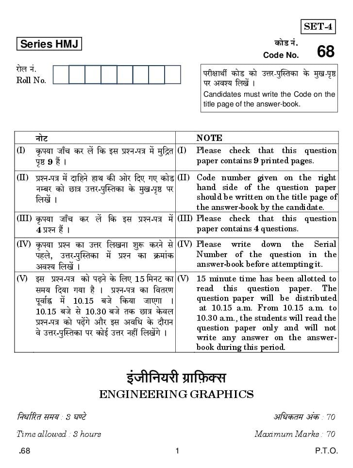
CBSE Class 12 Engineering Graphics Question Paper 2020
Finished viewing? Save it for later —
Download CBSE Class 12 Engineering Graphics Question Paper 2020 (PDF · 9 pages)About CBSE Class 12 Engineering Graphics Question Paper 2020
CBSE Class 12 Engineering Graphics Question Paper 2020 is available here for free download. Published by CBSE for Class 12, this question paper can be viewed online or downloaded as a PDF (9 pages). Candidates preparing for Class 12 can use CBSE Class 12 Engineering Graphics Question Paper 2020 to understand the exam pattern, the type of questions asked, and the overall difficulty level.
Frequently Asked Questions
How can I download CBSE Class 12 Engineering Graphics Question Paper 2020?
Open this page and click the Download button to save CBSE Class 12 Engineering Graphics Question Paper 2020 as a PDF. It is completely free on AglaSem Docs.
Is CBSE Class 12 Engineering Graphics Question Paper 2020 free to download?
Yes. CBSE Class 12 Engineering Graphics Question Paper 2020 can be viewed online and downloaded as a PDF free of cost on AglaSem Docs.
How many pages does CBSE Class 12 Engineering Graphics Question Paper 2020 have?
CBSE Class 12 Engineering Graphics Question Paper 2020 contains 9 pages, which you can read online or download together as a single PDF.
Where can I find more Class 12 study material?
You can find more Class 12 question papers, sample papers, syllabus, and answer keys on AglaSem Docs.
CBSE Class 12 Engineering Graphics Question Paper 2020 – Text
Read the full text of this question paper below — useful to quickly search, copy and reference the content online without downloading the PDF.
📄 View text version (9 pages)
Page 1
Series HMJ H$moS> Z§.
Code No. 68
amob Z§. narjmWu H$moS >H$mo CÎma-nwpñVH$m Ho$ _wI-n¥ð
Roll No. >na Adí` {bIo§ &
Candidates must write the Code on the
title page of the answer-book.
ZmoQ> NOTE
(I) H¥$n`m Om±M H$a b| {H$ Bg àíZ-nÌ _o§ _w{ÐV (I) Please check that this question
n¥ð> 9 h¢ & paper contains 9 printed pages.
(II) àíZ-nÌ _| Xm{hZo hmW H$s Amoa {XE JE H$moS (II) Code number given on the right
>Zå~a H$mo N>mÌ CÎma-nwpñVH$m Ho$ _wI-n¥ð> na hand side of the question paper
{bI| & should be written on the title page of
the answer-book by the candidate.
(III) H¥$n`m Om±M H$a b| {H$ Bg àíZ-nÌ _| (III) Please check that this question
>4 àíZ h¢ & paper contains 4 questions.
(IV) H¥$n`m àíZ H$m CÎma {bIZm ewê$ H$aZo go (IV) Please write down the Serial
nhbo, CÎma-nwpñVH$m _| àíZ H$m H«$_m§H$ Number of the question in the
Adí` {bI| & answer-book before attempting it.
(V) Bg àíZ-nÌ H$mo n‹T>Zo Ho$ {bE 15 {_ZQ >H$m (V) 15 minute time has been allotted to
g_` {X`m J`m h¡ & àíZ-nÌ H$m {dVaU read this question paper. The
nydm©• _| 10.15 ~Oo {H$`m OmEJm & question paper will be distributed
10.15 ~Oo go 10.30 ~Oo VH$ N>mÌ Ho$db at 10.15 a.m. From 10.15 a.m. to
10.30 a.m., the students will read the
àíZ-nÌ H$mo n‹T>|Jo Am¡a Bg Ad{Y Ho$ Xm¡amZ question paper only and will not
do CÎma-nwpñVH$m na H$moB© CÎma Zht {bI|Jo & write any answer on the answer-
book during this period.
B§Or{Z`ar J«m{µ\$Šg
ENGINEERING GRAPHICS
{ZYm©[aV g_` : 3 KÊQ>o A{YH$V_ A§H$ : 70
Time allowed : 3 hours Maximum Marks : 70
.68 1 P.T.O.
Page 2
(i) g^r àíZm| Ho$ CÎma Xr{OE &
(ii) `{X Amdí`H$ hmo, Vmo S´>mB§J erQ> Ho$ XmoZm| njm| H$m à`moJ H$a| &
(iii) g^r n[a_mn {_br_rQ>a _| h¢ &
(iv) `{X H$moB© n¡_mBe AZwnpñWV `m Ag§JV hmo, Vmo CgHo$ {bE Cn`wº$ _mZ H$s H$ënZm H$s
OmE &
(v) Eg.nr. : 46-2003 g§emo{YV H$moS> (àjonU Ho$ àW_ H$moU {d{Y Ho$ gmW) H$m nmbZ H$a| &
(vi) àíZ 2 Ho$ {H$gr ^r Ñí` (àjon) _| {N>no {H$Zmam| AWdm aoImAm| H$mo Z {XImE± &
(vii) àíZ 4 Ho$ AN>o{XV Ñí`m| (àjonm|) _| {N>no {H$Zmam| AWdm aoImAm| H$mo {XImE± &
(viii) àíZm| Ho$ AZwgma AnZo CÎma X| &
1. {ZåZ{b{IV ~hþ{dH$ënr` àíZm| Ho$ CÎma Xr{OE & ghr {dH$ën AnZr S´>mB§J erQ> na
Ambo{IV H$s{OE & 15=5
(i) àW_ H$moU àjonU nÕ{V _|
(A) dñVw àjonU gVh Am¡a Xe©H$ Ho$ ~rM _| AdpñWV hmoVr h¡ &
(B) àjonU gVh Xe©H$ Am¡a dñVw Ho$ ~rM _| AdpñWV hmoVr h¡ &
(C) Xe©H$ dñVw Am¡a àjonU gVh Ho$ ~rM _| AdpñWV hmoVm h¡ &
(D) dñVw Iå~m| Ho$ ~rM _| AdpñWV hmoVr h¡ &
(ii) EH$ dJm©H$ma My‹S>r {OgH$m gm§Ho${VH$ ì`mg 40 {_._r. Am¡a {nM 4 {_._r. H$mo
Zm{_V {H$`m OmVm h¡
(A) SE 40 4
(B) SQ 160
(C) SQ 40 4
(D) SE 160
(iii) EH$ J-~moëQ> Am_Vm¡a na dJm©H$ma Jbo Ho$ gmW àXmZ {H$`m OmVm h¡
(A) ~moëQ> _| VZmd ~‹T>mZo Ho$ {bE &
(B) H$gVo g_` ~moëQ> H$mo Ky_Zo go amoH$Zo Ho$ {bE &
(C) _erZ Qy>b Q>o~b _| BgHo$ BñVo_mb H$mo amoH$Zo Ho$ {bE &
(D) AÀN>m {XIZo Ho$ {bE &
.68 2
Page 3
(i) Attempt all the questions.
(ii) Use both sides of the drawing sheet, if necessary.
(iii) All dimensions are in millimetres.
(iv) Missing and mismatching dimensions, if any, may be suitably assumed.
(v) Follow the SP : 46-2003 revised codes (with first angle method of
projection).
(vi) In no view of question 2, hidden edges or lines are required.
(vii) In question 4, hidden edges or lines are to be shown in views without
section.
(viii) Give your answers according to questions.
1. Answer the following multiple choice questions. Print the correct choice
on your drawing sheet. 15=5
(i) In first angle method of projection
(A) The object lies between the observer and the plane of
projection.
(B) The plane of projection lies between the observer and the
object.
(C) The observer lies between the object and the plane of
projection.
(D) The object lies between the poles.
(ii) A square thread of nominal diameter 40 mm and pitch 4 mm is
designated as
(A) SE 40 4
(B) SQ 160
(C) SQ 40 4
(D) SE 160
(iii) A J-bolt is usually provided with a square neck to
(A) Add tension to the bolt.
(B) Prevent the bolt rotation while tightening.
(C) Prevent its use in machine tool table.
(D) To look better.
.68 3 P.T.O.
Page 4
(A) gm°Ho$Q> {gao Ho$ gmW N>‹S>, pñnJm°Q> {gao Ho$ gmW N>‹S>, {J~ Am¡a H$m°Q>a
(B) µâb¢O, N>‹S>o, {J~ Am¡a H$m°Q>a
(C) ñbrd, N>‹S>|, {J~ Am¡a H$m°Q>a
(D) \$moH©$ {gao Ho$ gmW N>‹S>, AmB© {gao Ho$ gmW N>‹S>, {J~ Am¡a H$m°Q>a
(v) Am_Vm¡a na âboQ> ~oëQ> nwbr _| [a_ na H«$mCqZJ àXmZ H$s hmoVr h¡
(A) 2 {_._r.
(B) 20 {_._r.
(C) 50 {_._r.
(D) 100 {_._r.
2. (i) EH$ 70 {_._r. bå~o g_n[a_mU n¡_mZo H$mo ~ZmBE & 4
(ii) EH$ e§Hw$ (ì`mg 60 {_._r., D±$MmB© 70 {_._r.) AnZo AmYma go EM.nr. na aIm
h¡ & BgH$m Aj EM.nr. na bå~dV² h¡ & BgH$m EH$ g_n[a_mU àjon ~ZmBE &
Aj H$mo {XImBE Am¡a XoIZo H$s {Xem H$m g§Ho$V Xr{OE & g^r Am`m_ Xr{OE & 7
(iii) EH$ j¡{VO n§M^wO {àµÁ_ (AmYma ^wOm 25 {_._r., Aj H$s b§~mB© 60 {_._r.),
AnZo EH$ Am`VmH$ma \$bH$ H$s Amoa go EH$ Š`y~ (^wOm 50 {_._r.) Ho$ D$nar
gVh na ~rMm|-~rM pñWV h¡ & Š`y~ H$m Aj EM.nr. na bå~dV² h¡ Am¡a {àµÁ_ H$m
Aj dr.nr. na bå~dV² h¡ & R>mogm| Ho$ g§`moOZ H$m g_n[a_mU àjon ~ZmBE & g_mZ
Aj H$mo {XImBE Am¡a XoIZo H$s {Xem H$m g§Ho$V Xr{OE & g^r Am`m_ Xr{OE & 13
3. (i) ~‹T>o hþE {nM H$mo 40 {_._r. boVo hþE EH$ ~r.Eg.S>ãë`y. ñH«y$ W«oS> (BSW
Screw thread) H$m _mZH$ àmo\$mBb 1 : 1 H$s _mnZr _| ~ZmBE & _mZH$ Am`m_
Xr{OE & 8
AWdm
àË`oH$ ßboQ> H$s _moQ>mB© 9 {_._r. boVo hþE EH$ qgJb [adoQ>oS> b¡n Om°B§Q> (Single
reveted lap joint) Ho$ N>o{XV gå_wI Ñí` H$mo 1 : 1 H$s _mnZr na ~ZmBE &
_mZH$ Am`m_ Xr{OE & 8
(ii) EH$ j¡{VO H$m°ba ñQ>°S> (Horizontal Collar Stud) ì`mg 15 {__r H$m
gå_wI Ñí` Am¡a nmíd© Ñí` _wŠVhñV ~ZmBE & BgHo$ Aj H$mo EM.nr. Am¡a dr.nr.
Ho$ g_mÝVa a{IE & _mZH$ Am`m_ Xr{OE & 5
AWdm
Aj H$mo grYm aIVo hþE EH$ Mrg hoS> ñH«y$ (Cheese head screw) ì`mg
20 {__r H$m gå_wI Ñí` Am¡a D$nar Ñí` _wŠVhñV ~ZmBE & _mZH$ Am`m_
Xr{OE & 5
.68 4
Page 5
and Cotter Joint ?
(A) Rod with socket end, rod with spigot end, gib and cotter
(B) Flanges, rods, gib and cotter
(C) Sleeve, rods, gib and cotter
(D) Rod with fork end, eye end rod, gib and cotter
(v) The crowning provided on the rim of a flat belt pulley is usually
(A) 2 mm
(B) 20 mm
(C) 50 mm
(D) 100 mm
2. (i) Construct an isometric scale of length 70 mm. 4
(ii) A cone (base diameter 60 mm, height 70 mm) is resting on its base
on H.P. Its axis is perpendicular to H.P. Draw its isometric
projection. Show the axis and indicate the direction of viewing.
Give all the dimensions. 7
(iii) A horizontal pentagonal prism (base edge 25 mm, length of axis 60
mm) is resting on one of its rectangular faces, centrally on the top
surface of a cube (side 50 mm). The axis of the cube is
perpendicular to H.P. and the axis of the prism is perpendicular to
V.P. Draw the isometric projection of the combination of solids.
Show the common axis and indicate the direction of viewing. Give
all the dimensions. 13
3. (i) Draw to scale 1 : 1, the standard profile of a British Standard
Whitworth thread (BSW), taking enlarged pitch as 40 mm. Give
standard dimensions. 8
OR
Draw to scale 1 : 1, the sectional front view of a Single Riveted
Lap Joint for joining the plates, each of thickness 9 mm. Give
standard dimensions. 8
(ii) Sketch freehand, the front view and side view of a Horizontal
Collar Stud of diameter 15 mm. Keep its axis parallel to VP and
HP. Give standard dimensions. 5
OR
Sketch freehand, the front view and top view of a Cheese Head
Screw of diameter 20 mm keeping its axis vertical. Give standard
dimensions. 5
.68 5 P.T.O.
Page 6
h¡ & BZ nwµOm] H$mo R>rH$ go EH${ÌV H$aHo$, 1 : 1 H$s _mnZr _| BgHo$ {ZåZ{b{IV Ñí`m| H$mo
~ZmBE :
(i) ~m`m± AÕ© H$mQ> g{hV, gå_wI Ñí` & 14
(ii) D$nar Ñí` & 8
erf©H$ VWm à`wŠV _mnZr Ambo{IV H$s{OE & àjon {M• ~ZmBE & 6 _hÎdnyU© {d_mE±
Xr{OE & 6
AWdm
.68 6
Page 7
parts correctly and then draw to scale 1 : 1 its following views :
(i) Front view left half in section 14
(ii) Top view 8
Print the title and scale used. Draw projection symbol. Give 6 important
dimensions. 6
OR
.68 7 P.T.O.
Page 8
g§J«{hV Ñí`m| H$mo {XIm`m J`m h¡ & BgHo$ nwµOm] H$mo R>rH$ go AbJ H$aHo$ BgHo$ {ZåZ{b{IV
nwµOm] Ho$ {ZåZ{b{IV Ñí`m| H$mo 1 : 1 H$s _mnZr _| ~ZmBE & EM.nr. Am¡a dr.nr. Ho$ gå~ÝY
_| Xr JB© âb¢O Am¡a emµâQ> XmoZm| H$s pñW{V, dhr a{IE &
(i) âb¢O (FLANGE) A
(a) D$nar AY©-H$mQ> g{hV gå_wI Ñí` 8
(b) ~m`m± nmíd© Ñí` 7
(ii) emµâQ> (SHAFT) B
(a) gå_wI Ñí` 4
(b) Xm`m± nmíd© Ñí` 3
XmoZm| Ho$ erf©H$ VWm à`wŠV _mnZr Ambo{IV H$s{OE & àjon {M• ~ZmBE & 6 _hÎdnyU©
{d_mE± Xr{OE & 6
.68 8
Page 9
Disassemble the parts correctly and then draw to scale 1 : 1 its following
views of the following components. Keep the same position of both flange
and shaft with respect to H.P. and V.P.
(i) FLANGE A
(a) Front view upper half in section 8
(b) Left side view 7
(ii) SHAFT B
(a) Front view 4
(b) Right side view 3
Print the titles of both and scale used. Draw the projection symbol. Give
6 important dimensions. 6
.68 9 P.T.O.
Document Details
| Board / Org | CBSE |
| Exam | Class 12 |
| Type | Question Paper |
| Pages | 9 |
| Updated | 22 Jul 2026 |