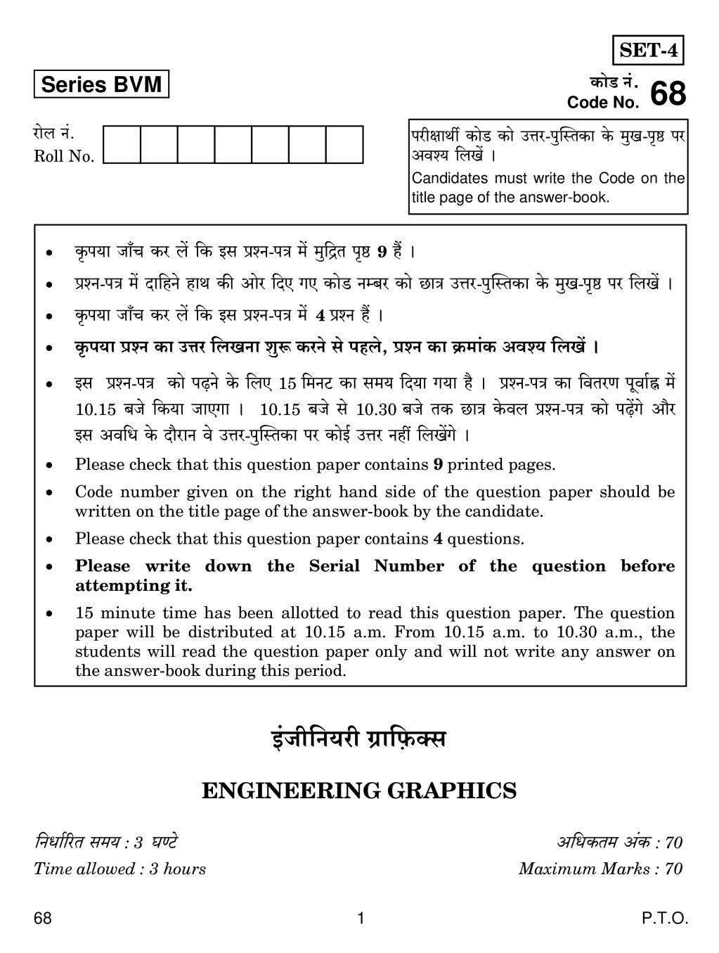
CBSE Class 12 Engineering Graphics Question Paper 2019
Finished viewing? Save it for later —
Download CBSE Class 12 Engineering Graphics Question Paper 2019 (PDF · 9 pages)About CBSE Class 12 Engineering Graphics Question Paper 2019
CBSE Class 12 Engineering Graphics Question Paper 2019 is available here for free download. Published by CBSE for Class 12, this question paper can be viewed online or downloaded as a PDF (9 pages). Candidates preparing for Class 12 can use CBSE Class 12 Engineering Graphics Question Paper 2019 to understand the exam pattern, the type of questions asked, and the overall difficulty level.
Frequently Asked Questions
How can I download CBSE Class 12 Engineering Graphics Question Paper 2019?
Open this page and click the Download button to save CBSE Class 12 Engineering Graphics Question Paper 2019 as a PDF. It is completely free on AglaSem Docs.
Is CBSE Class 12 Engineering Graphics Question Paper 2019 free to download?
Yes. CBSE Class 12 Engineering Graphics Question Paper 2019 can be viewed online and downloaded as a PDF free of cost on AglaSem Docs.
How many pages does CBSE Class 12 Engineering Graphics Question Paper 2019 have?
CBSE Class 12 Engineering Graphics Question Paper 2019 contains 9 pages, which you can read online or download together as a single PDF.
Where can I find more Class 12 study material?
You can find more Class 12 question papers, sample papers, syllabus, and answer keys on AglaSem Docs.
CBSE Class 12 Engineering Graphics Question Paper 2019 – Text
Read the full text of this question paper below — useful to quickly search, copy and reference the content online without downloading the PDF.
📄 View text version (9 pages)
Page 1
Series BVM H$moS> Z§.
Code No. 68
amob Z§. narjmWu H$moS >H$mo CÎma-nwpñVH$m Ho$ _wI-n¥ð >na
Roll No. Adí` {bIo§ &
Candidates must write the Code on the
title page of the answer-book.
H¥$n`m Om±M H$a b| {H$ Bg àíZ-nÌ _o§ _w{ÐV n¥ð> 9 h¢ &
àíZ-nÌ _| Xm{hZo hmW H$s Amoa {XE JE H$moS >Zå~a H$mo N>mÌ CÎma-nwpñVH$m Ho$ _wI-n¥ð> na {bI| &
H¥$n`m Om±M H$a b| {H$ Bg àíZ-nÌ _| >4 àíZ h¢ &
H¥$n`m àíZ H$m CÎma {bIZm ewê$ H$aZo go nhbo, àíZ H$m H«$_m§H$ Adí` {bI| &
Bg àíZ-nÌ H$mo n‹T>Zo Ho$ {bE 15 {_ZQ >H$m g_` {X`m J`m h¡ & àíZ-nÌ H$m {dVaU nydm©• _|
10.15 ~Oo {H$`m OmEJm & 10.15 ~Oo go 10.30 ~Oo VH$ N>mÌ Ho$db àíZ-nÌ H$mo n‹T>|Jo Am¡a
Bg Ad{Y Ho$ Xm¡amZ do CÎma-nwpñVH$m na H$moB© CÎma Zht {bI|Jo &
Please check that this question paper contains 9 printed pages.
Code number given on the right hand side of the question paper should be
written on the title page of the answer-book by the candidate.
Please check that this question paper contains 4 questions.
Please write down the Serial Number of the question before
attempting it.
15 minute time has been allotted to read this question paper. The question
paper will be distributed at 10.15 a.m. From 10.15 a.m. to 10.30 a.m., the
students will read the question paper only and will not write any answer on
the answer-book during this period.
B§Or{Z`ar J«m{µ\$Šg
ENGINEERING GRAPHICS
{ZYm©[aV g_` : 3 KÊQ>o A{YH$V_ A§H$ : 70
Time allowed : 3 hours Maximum Marks : 70
68 1 P.T.O.
Page 2
(i) g^r àíZm| Ho$ CÎma Xr{OE &
(ii) `{X Amdí`H$ hmo, Vmo S´>mB§J erQ> Ho$ XmoZm| njm| H$m à`moJ H$a| &
(iii) g^r n[a_mn {_br_rQ>a _| h¢ &
(iv) `{X H$moB© n¡_mBe AZwnpñWV `m Ag§JV hmo, Vmo CgHo$ {bE Cn`wº$ _mZ H$s H$ënZm H$s
OmE &
(v) Eg.nr. : 46-2003 g§emo{YV H$moS> (àjonU Ho$ àW_ H$moU {d{Y Ho$ gmW) H$m nmbZ H$a| &
(vi) àíZ 2 Ho$ {H$gr ^r Ñí` (àjon) _| {N>no {H$Zmam| AWdm aoImAm| H$mo Z {XImE± &
(vii) àíZ 4 Ho$ AN>o{XV Ñí`m| (àjonm|) _| {N>no {H$Zmam| AWdm aoImAm| H$mo {XImE± &
(viii) àíZm| Ho$ AZwgma AnZo CÎma X| &
General Instructions :
(i) Attempt all the questions.
(ii) Use both sides of the drawing sheet, if necessary.
(iii) All dimensions are in millimetres.
(iv) Missing and mismatching dimensions, if any, may be suitably assumed.
(v) Follow the SP : 46-2003 revised codes (with first angle method of
projection).
(vi) In no view of question 2, hidden edges or lines are required.
(vii) In question 4, hidden edges or lines are to be shown in views without
section.
(viii) Give your answers according to questions.
68 2
Page 3
Ambo{IV H$s{OE & 1×5=5
(i) Am_Vm¡a na B§Or{Z`ar H$m`m] Ho$ {bE {H$g àjonU H$m BñVo_mb hmoVm h¡ ?
(A) {MÌ àjonU
(~) g_n[a_mU àjonU
(g) namoj àjonU
(X) n[aàoú` àjonU
(ii) {ZåZ{b{IV _| go H$m¡Z-gm EH$ ñH«y$ no`a h¡ ?
(A) ~moëQ> Am¡a Z°Q>
(~) em°µâQ> Am¡a H$s
(g) {J~ Am¡a H$m°Q>a
(X) [adoQ> Am¡a ßboQ>
(iii) EH$ hþH$ ~moëQ> _| ~moëQ> H$m XÊS>
(A) Ho$db EH$ nwµO} Ho$ {N>Ð _| go JwµOaVm h¡
(~) Xmo nwµOm] Ho$ {N>Ðm| _| go JwµOaVm h¡
(g) {H$gr ^r nwµO} _| go Zht JwµOaVm h¡
(X) EH$ H$s-hmob go JwµOaVm h¡
(iv) EH$ ~wíS> {~`[a¨J _|, {~`[a¨J Ho$ Vbo H$mo [agog ~Zm`m OmVm h¡
(A) brH$-àyµ\$ ~ZmZo Ho$ {bE
(~) em°µâQ>m| H$mo Omo‹S>Zo Ho$ {bE
(g) ~we H$mo {~R>mZo Ho$ {bE
(X) n¥îR> na ~ohVa pñWaVm àXmZ H$aZo Ho$ {bE
(v) EH$ Q>Z©~H$b g_wƒ` _| Hw$b nwµOm] H$s g§»`m hmoVr h¡
(A) 1
(~) 2>
(g) 3
(X) 4>
68 3 P.T.O.
Page 4
on your drawing sheet.
(i) The projection generally used for engineering practice is
(a) Picture projection
(b) Isometric projection
(c) Oblique projection
(d) Perspective projection
(ii) Which one among the following is called screw pair ?
(a) Bolt and nut
(b) Shaft and key
(c) Gib and cotter
(d) Rivet and plate
(iii) In a Hook bolt, the shank of the bolt
(a) Passes through a hole in one part only
(b) Passes through the holes in two parts
(c) Does not pass through any of the parts
(d) Passes through a key-hole
(iv) In bushed bearing, the sole of the bearing is recessed for
(a) Making it leak-proof
(b) Joining the shafts
(c) Fitting the bush
(d) Better stability on the surface
(v) The total number of components in turnbuckle assembly is
(a) 1
(b) 2
(c) 3
(d) 4
68 4
Page 5
(ii) EH$ CbQ>m n§M^wOmH$ma {nam{_S> H$m {N>ÞH$ (AmYma ^wOm 25 {__r, D$nar ^wOm
40 {__r Am¡a D±$MmB© 60 {__r) EM.nr. na pñWV h¡, {OgH$m Aj EM.nr. na
bå~dV² h¡ & BgH$s EH$ AmYma ^wOm dr.nr. Ho$ g_mZm§Va Am¡a Xe©H$ Ho$ H$ar~ h¡ &
BgH$m EH$ g_n[a_mU àjon ~ZmBE & Aj H$mo {XImBE Am¡a XoIZo H$s {Xem
Xem©BE & g^r Am`m_ Xr{OE & 7
(iii) EH$ ~obZ (AmYma ì`mg 50 {__r Am¡a D±$MmB© 50 {__r) AnZo Aj H$mo EM.nr.
na bå~dV² aIVo hþE EH$ j¡{VO {ÌH$moUr` {àµÁ_ ({Ì^wO H$s ^wOm 40 {__r Am¡a
Aj H$s bå~mB© 70 {__r) Ho$ erf© Am`VmH$ma \$bH$ Ho$ D$na d ~rMm|-~rM pñWV
h¡ & {àµÁ_ AnZo bå~r ^wOm H$s Amoa go AnZo Aj Ho$ gmW dr.nr. Am¡a EM.nr.
XmoZm| Ho$ g_mZm§Va pñWV h¡ & R>mogm| Ho$ g§`moOZ H$m g_n[a_mU àjon ~ZmBE & àË`oH$
R>mog H$s Aj Am¡a XoIZo H$s {Xem H$m g§Ho$V {XImBE & g^r Am`m_ Xr{OE & 13
(i) Construct an isometric scale.
(ii) An inverted frustum of a pentagonal pyramid (base edge 25 mm,
top edge 40 mm and height 60 mm) is resting on H.P., with its axis
perpendicular to H.P. One of its base edges is parallel to V.P. and
nearer to the observer. Draw its isometric projection. Show the
axis and indicate the direction of viewing. Give all the dimensions.
(iii) A cylinder (base diameter 50 mm and height 50 mm) with its axis
perpendicular to H.P. is placed centrally on the top rectangular
face of a horizontal triangular prism (side of triangle 40 mm and
length of axis 70 mm). The prism is resting on its long edge with
its axis parallel to both V.P. and H.P. Draw the isometric
projection of the combination of solids. Show the axis of each solid
and indicate the direction of viewing. Give all the dimensions.
3. (i) ~‹T>r hþB© {nM H$mo 40 {__r boVo hþE, 1 : 1 H$s _mnZr _| EH$ _rQ>ar W«oS> EŠgQ>Z©b
(Metric thread external) H$m _mZH àmoµ\$mBb ~ZmBE & _mZH$ Am`m_
Xr{OE & 8
AWdm
Aj H$mo j¡{VO Ed§ dr.nr. Am¡a EM.nr. XmoZm| Ho$ g_mZm§Va aIVo hþE, 1 : 1 H$s
_mnZr _| EH$ fQ²>^wOmH$ma hoS>oS> ~moëQ>> (Hexagonal headed bolt) ì`mg
20 {__r H$m gå_wI X¥í` VWm nmíd© Ñí` ~ZmBE & _mZH$ Am`m_ Xr{OE &
(ii) Aj H$mo D$Üdm©Ya aIVo hþE, M20 {__r _mn dmbo EH$ ñQ>°S> dJm©H$ma Jbo Ho$
gmW (Stud with square neck) H$m gå_wI Ñí` Am¡a D$nar Ñí` _wº$hñV
~ZmBE & _mZH$ Am`m_ Xr{OE & 5
AWdm
Aj H$mo j¡{VO Ed§ dr.nr. Am¡a EM.nr. XmoZm| Ho$ g_mZm§Va aIVo hþE, M10 {__r _mn
dmbo EH$ gm°Ho$Q> hoS> _erZ ñH«y$ (Socket head machine screw) H$m
gå_wI Ñí` _wº$hñV ~ZmBE & _mZH$ Am`m_ Xr{OE &
68 5 P.T.O.
Page 6
external, taking enlarged pitch as 40 mm. Give standard
dimensions.
OR
Draw to scale 1 : 1, the front view and side view of a Hexagonal
headed bolt of diameter 20 mm, keeping the axis horizontal and
parallel to both V.P. and H.P. Give standard dimensions.
(ii) Sketch freehand the front view and top view of a Stud with
square neck of size M20 mm, keeping the axis vertical. Give
standard dimensions.
OR
Sketch freehand the front view of a Socket head machine screw
of size M10 mm keeping the axis horizontal and parallel to both
V.P. and H.P. Give standard dimensions.
4. {MÌ 1 _|, EH$ {J~ Am¡a H$m°Q>a Ádm°B§Q> (GIB AND COTTER JOINT) Ho$ nwµOm] H$m
{ddaU {XIm`m J`m h¡ & BZ nwOm] H$mo R>rH$ go EH$Ì H$aHo$, 1 : 1 H$s _mnZr _| BgHo$
{ZåZ{b{IV Ñí`m| H$mo ~ZmBE :
(i) D$nar AY©-H$mQ> g{hV, gå_wI Ñí` & 16
(ii) ~m`m± nmíd© Ñí` & 6
erf©H$ VWm à`wº$ _mnZr Ambo{IV H$s{OE & àjon {M• ~ZmBE & N>h _hÎdnyU© {d_mE±
Xr{OE & 6
Figure 1 shows the details of the parts of a GIB AND COTTER JOINT.
Assemble these parts correctly and then draw the following views using
scale 1 : 1.
(i) Front view, upper half in section.
(ii) Left side view.
Print the title and the scale used. Draw the projection symbol. Give
six important dimensions.
68 6
Page 7
68 7 P.T.O.
Page 8
g§J«hrV Ñí` H$mo {XIm`m J`m h¡ & BgHo$ nwµOm] H$mo AbJ H$aHo$ BgHo$ {ZåZ{b{IV nwµOmªo Ho$
{ZåZ{b{IV Ñí`m| H$mo 1 : 1 H$s _mnZr _| ~ZmBE & nwbr Am¡a Am`VmH$ma Q>ona H$s XmoZm| H$s,
EM.nr. Am¡a dr.nr. Ho$ gmnoj pñW{V dhr a{IE &
(i) nwbr (PULLEY) :
(A) D$nar AY©-H$mQ> g{hV, gå_wI Ñí` & 8
(~) Xm`m± nmíd© Ñí` & 8
(ii) Am`VmH$ma g§H$ Q>ona H$s (RECTANGULAR SUNK TAPER KEY) :
(A) gå_wI Ñí` & 3
(~) ~m`m± nmíd© Ñí` & 3
XmoZm| Ho$ erf©H$ VWm à`wº$ _mnZr Ambo{IV H$s{OE & àjon {M• ~ZmBE & N>h _hÎdnyU©
{d_mE± Xr{OE & 6
Figure 2 shows the assembly of a SOLID CAST IRON PULLEY.
Disassemble the parts and then draw the following views of the following
components to scale 1 : 1, keeping the same position of both Pulley and
Rectangular taper key with respect to H.P. and V.P.
(i) PULLEY :
(a) Front view, upper half in section.
(b) Right side view.
(ii) RECTANGULAR SUNK TAPER KEY :
(a) Front view.
(b) Left side view.
Print the titles of both and the scale used. Draw the projection symbol.
Give six important dimensions.
68 8
Page 9
Document Details
| Board / Org | CBSE |
| Exam | Class 12 |
| Type | Question Paper |
| Pages | 9 |
| Updated | 30 Apr 2026 |