CBSE Class 12 Sample Paper 2027 Solution (Marking Scheme) for Physics
Finished viewing? Save it for later —
Download CBSE Class 12 Sample Paper 2027 Solution (Marking Scheme) for Physics (PDF · 15 pages)About CBSE Class 12 Sample Paper 2027 Solution (Marking Scheme) for Physics
CBSE Class 12 Sample Paper 2027 Solution (Marking Scheme) for Physics is available here for free download. Published by CBSE for Class 12, this solution can be viewed online or downloaded as a PDF (15 pages). Candidates preparing for Class 12 can use CBSE Class 12 Sample Paper 2027 Solution (Marking Scheme) for Physics to understand the exam pattern, the type of questions asked, and the overall difficulty level.
Frequently Asked Questions
How can I download CBSE Class 12 Sample Paper 2027 Solution (Marking Scheme) for Physics?
Open this page and click the Download button to save CBSE Class 12 Sample Paper 2027 Solution (Marking Scheme) for Physics as a PDF. It is completely free on AglaSem Docs.
Is CBSE Class 12 Sample Paper 2027 Solution (Marking Scheme) for Physics free to download?
Yes. CBSE Class 12 Sample Paper 2027 Solution (Marking Scheme) for Physics can be viewed online and downloaded as a PDF free of cost on AglaSem Docs.
How many pages does CBSE Class 12 Sample Paper 2027 Solution (Marking Scheme) for Physics have?
CBSE Class 12 Sample Paper 2027 Solution (Marking Scheme) for Physics contains 15 pages, which you can read online or download together as a single PDF.
Where can I find more Class 12 study material?
You can find more Class 12 question papers, sample papers, syllabus, and answer keys on AglaSem Docs.
CBSE Class 12 Sample Paper 2027 Solution (Marking Scheme) for Physics – Text
Read the full text of this solution below — useful to quickly search, copy and reference the content online without downloading the PDF.
📄 View text version (16 pages)
Page 1
CBSE Class 12 Sample
Paper 2027 Solution
(Marking Scheme) for
Physics
EXAM YEAR TYPE SUBJECT
CBSE Class 12 2027 Solutions Physics
Notes · Sample Papers · Previous Year Papers · Mock Tests
Page 2
m .co
m .co s e m
se
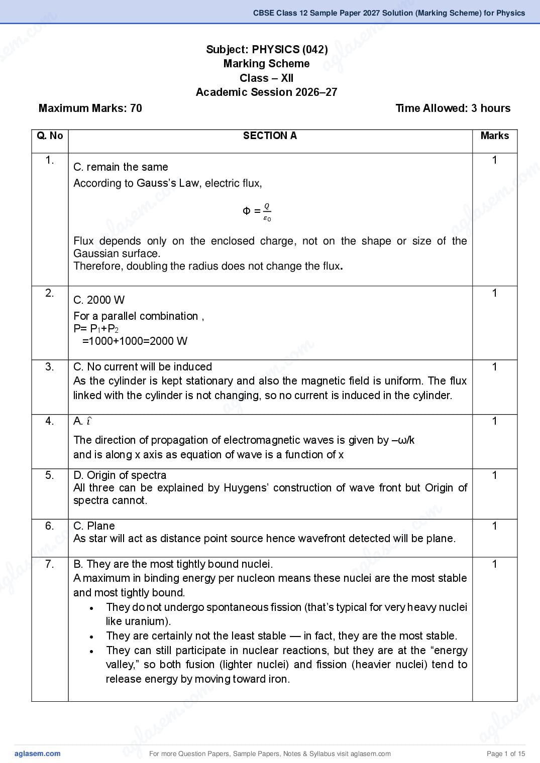
Subject: PHYSICS (042)
g l a
Marking Scheme
Class – XII
a
Academic Session 2026–27
Maximum Marks: 70 Time Allowed: 3 hours
Q. No SECTION A Marks
1. 1
C. remain the same
m
m
According to Gauss’s Law, electric flux,
.co
.co s e m
em a
𝑄
Ф=
as 𝜀0
g l
l a
ag
Flux depends only on the enclosed charge, not on the shape or size of the
Gaussian surface.
Therefore, doubling the radius does not change the flux.
2. 1
C. 2000 W
For a parallel combination ,
P= P1+P2
=1000+1000=2000 W
m
3. C. No current will be induced .co 1
s em
As the cylinder is kept stationary and also the magnetic field is uniform. The flux
l a
linked with the cylinder is not changing, so no current is induced in the cylinder.
4. A. 𝑖̂
ag 1
The direction of propagation of electromagnetic waves is given by –ω/k
and is along x axis as equation of wave is a function of x
5. D. Origin of spectra 1
All three can be explained by Huygens’ construction of wave front but Origin of
spectra cannot.
m
6.
c. o
m
C. Plane
m .co 1
e
As star will act as distance point source hence wavefront detected will be plane.
s
s em7. B. They are the most tightly bound nuclei. g l a 1
g la a are the most stable
A maximum in binding energy per nucleon means these nuclei
a and most tightly bound.
They do not undergo spontaneous fission (that’s typical for very heavy nuclei
like uranium).
They are certainly not the least stable — in fact, they are the most stable.
They can still participate in nuclear reactions, but they are at the “energy
valley,” so both fusion (lighter nuclei) and fission (heavier nuclei) tend to
release energy by moving toward iron.
m .
.co s e m
s em l a
g la ag
a For more Question Papers, Sample Papers, Notes & Syllabus visit Page 1 of 15
Page 3
As the ball is dipped in liquid nitrogen, its temperature becomes less than the critical
temperature and it becomes a superconductor. In this state, the ball becomes
diamagnetic.
9. B. 5 A 1
The Wheatstone bridge is balanced, because
2Ω 3Ω
= .
4Ω 6Ω
The 5 Ω resistance is ineffective, we now have-
(2 Ω + 4 Ω) and (3 Ω + 6 Ω) resistances in parallel.
6𝑋9 18
RAB = = Ω
6+9 5
Now, I= V/R
18
Or, I= A =5A
18/5
For Visually Impaired Students only
B. R
In the balanced condition, the resistance R of the galvanometer is ineffective.
We have (R+R) and (R+R) resistances in parallel.
2𝑅 𝑋 2𝑅
Req= =R
2𝑅+2𝑅
10. A. 5:3 1
Here P1=60 W , P2=100 W
𝑉2 𝑉2
R1= 𝑃 and R2 = 𝑃
1 2
𝑅1 𝑃2 100
⸫𝑅 = = = 5: 3
𝑃 2 1 60
11. C. 22 km 1
Typical nuclear radius ≈ 10-15m (1 femtometer).
Atom radius (electron orbit, roughly Bohr radius) ~ 10-10 m
Ratio of atom size to nucleus size ~ 105.
Football (nucleus) radius ~ 22 cm = 0.22 m.
Multiply by 105
0.22m×105=22,000m=22km.
12. C. 5 π μ T 1
μ 𝐼 4π x 10−7 x 5
B= 0 = 𝑇 =5π x10−6 𝑇 =5 π μ T
4𝑅 4 𝑥 0.10
For more Question Papers, Sample Papers, Notes & Syllabus visit Page 2 of 15
Page 4
m .co
m .co For Questions 13 to 16, two statements are given –one labelled Assertion (A)
s e m
se and other labelled Reason (R). Select the correct answer to these questions
g l a
from the options as given below. a
A. both Assertion and Reason are true and Reason is the correct explanation of
Assertion.
B. both Assertion and Reason are true but Reason is not the correct explanation
of Assertion.
C. Assertion is true but Reason is false.
D. both Assertion and Reason are false.
o m
m
o Reason are true but Reason is not the correct explanation of 1em . c
13.
c
B. both Assertion and
. s
Assertion.
s em g l a
l a a
ag pass undeflected; electron mass has negligible deflecting effect on
Explanation:
particles
Both are true; most of the space is empty (nucleus tiny), so alpha
energetic alpha particles, as reason for statement is “most of the space is empty
(nucleus tiny)”
14. A. both Assertion and Reason are true and Reason is the correct explanation of 1
Assertion.
m
.co
Explanation: Both true and R explains A; lens maker's formula uses relative index
µ
( 𝑙𝑒𝑛𝑠 - 1), so in water the relative refractive index decreases and f
µ𝑚𝑒𝑑𝑖𝑢𝑚
e m
increases.
la s
g
15. C. Assertion is true but Reason a
is false 1
Fringe width in YDSE is inversely proportional to the slit separation and directly
proportional to the wavelength of light.
16. D. both Assertion and Reason are false. 1
Electrons in a conductor move freely.
m
mWhen an external field is applied, charges rearrange until the internal field they
.co
m .co create exactly cancels the external field.
s e m
s e This is the reason the net internal field becomes zero.
g l a
g la a
a SECTION B
𝑐
17. I. Refractive index of medium (µ) =
𝑣𝑚𝑒𝑑𝑖𝑢𝑚
C= 3 × 10⁸m/s
2𝜋 ×1018
½
Vmedium= 𝜋 × 1010 = 2 × 10⁸ m/s
3 × 10⁸
µ =2 × 108 = 1.5 ½
m .
.co
II. Angular frequency (ω)= 2π × 1018 rad s-1
½
e m
em l as
las ag
ag For more Question Papers, Sample Papers, Notes & Syllabus visit Page 3 of 15
Page 5
Or, = 1018 s-1 ½
- This frequency correspond to X Ray
18. The nature of the path of free electrons in a conductor differs depending on whether
an electric field is present or not:
a. In the presence of an electric field
Free electrons experience a net force opposite to the direction of the electric 1
field.
This causes them to drift slowly in the direction opposite to the field (since
electrons are negatively charged).
Despite this drift, electrons still undergo frequent collisions with atoms in the
conductor, resulting in a zigzag or random motion superimposed with a net
drift.
This net movement of electrons constitutes an electric current.
b. In the absence of an electric field 1
Electrons move randomly due to thermal energy.
There is no net movement of electrons in any particular direction.
The motion is random and chaotic, similar to the movement of gas
molecules.
As a result, no electric current flows in the conductor.
19. At the midpoint, distance from both charges is d/2 ½
Potential due to one charge +q at the midpoint of the line:
V1 =
𝑘𝑞
𝑑 =
2𝑘𝑞 ½
𝑑
2
2𝑘𝑞 4𝑘𝑞
Potential due to both charges; V = 2 x = ½
𝑑 𝑑
4𝑘𝑞 ½
Work done by external gent : W = qV = q ( ) = 4𝑘𝑞 2 /𝑑
𝑑
20(A) Given:
Relative magnetic permeability, μr=800
Since the relative permeability is much greater than 1, the material is a 1
ferromagnetic material.
Properties:
1. Ferromagnetic materials are strongly attracted by a magnetic field because
½ x2
they have a very high value of magnetic permeability.
2. They can retain magnetism even after the external magnetic field is
removed, meaning they show hysteresis and can be made into permanent
magnets.
For more Question Papers, Sample Papers, Notes & Syllabus visit Page 4 of 15
Page 6
om Gauss’s law for magnetism states that the net magnetic fluxemthrough any closed .co
c. 20(B) s 1
e m l a
s surface is always zero:
⃗⃗⃗ 𝑑 𝑆=0
Ф =∮ 𝐵.
B ag
This means that the magnetic field lines neither begin nor end at any point.
Significance: ½x2
Magnetic monopoles do not exist
m
Magnetic field lines always form continuous loops
c o m m .co
. e
emthey represent the unique set of colored lines emitted whenglas
21(A) I. Hydrogen spectral lines are considered to be a fingerprint of the element 1
becauses
la atoms transit between energy levels. This phenomenon, known aas
g
hydrogen
athe line spectrum, is a result of the quantized energy levels of electrons in the
hydrogen atom. Each spectral line corresponds to a specific energy
transition, and the distinct pattern of these lines allows for the identification of
hydrogen in various environments.
II. The minimum energy of a photon that can ionize an electron in a hydrogen
atom is 13.6 eV. This is the ionization energy required to remove the electron
m
from its ground considering all the energy is transferred to electron.
.co
21(B) Postulate:
s em
g la around the nucleus in certain discrete
a
Bohr postulated that electrons revolve
circular orbits without radiating energy. His quantization condition is: mvr =
𝑛ℎ
1
2𝜋
Where:
m = mass of the electron
v = velocity of the electron
r = radius of the orbit
om
n = principal quantum number
m c.hypothesis:
c. o Explanation of stationary orbits using de Broglie
s e m wave with
em wavelength: a
According to de Broglie, a moving electron behaves like a matter
s g l
la a
ag λ=h/mv
1
For an orbit to be stable (stationary), the electron wave must form a standing wave
around the nucleus. This is possible only when the circumference of the orbit is an
integral multiple of the wavelength:
2πr = nλ
Substituting λ=h/mv
m .
.co s e m
s em l a
g la ag
a For more Question Papers, Sample Papers, Notes & Syllabus visit Page 5 of 15
Page 7
Or, mvr =nh/2π
This is exactly Bohr’s quantization condition.
Hence, de Broglie hypothesis explains Bohr’s stationary orbits as those orbits in
which the electron’s matter wave forms a standing wave, leading to stable, non-
radiating orbits.
SECTION C
22. Metals: Overlapping bands or partially filled conduction band; free electrons yield
high conductivity.
Insulators: Large band gap; negligible thermal excitation at room temperature; poor 1
conductivity.
Semiconductors: Moderate band gap; thermally/optically excited carriers; 1
conductivity can be varied with doping.
Diamond vs tin:
Diamond (C): Strong network, large gap (~ 5.4 eV); insulator at room temperature.
1
Tin (Sn): Metallic bonding with overlapping bands; conductor due to available states
at Fermi level.
Conclusion: Band gap magnitude controls room-temperature carrier availability and
hence conductivity.
23. I. The internal resistance of a car battery decreases with increase in 1
temperature. Therefore, on a warm day a car battery gives large current which
helps in starting the car engine.
II. It is because our body is sensitive to minute currents even as low as a few 1
mA.
III. When the temperature of the heater becomes greater than the temperature of 1
its surroundings, it begins to lose heat to surroundings. A stage is reached
when the rate of production of heat becomes equal to the rate of loss of heat
and the temperature becomes constant.
24. Z= 8 protons, N= 8 neutrons.
Sum of nucleon masses:
mpZ + mnN = 8(1.00727) + 8(1.00866)
=8.05816 + 8.06928 = 16.12744 u 1
Mass defect
Δm =16.12744 – 15.99493 = 0.132514
Binding energy
B= Δm × 931.5 = 0.13251 × 931.5 ≈ 123.4 MeV 1
Binding energy per nucleon
𝐵 123.4
= ≈ 7.71 MeV 1
𝐴 16
For more Question Papers, Sample Papers, Notes & Syllabus visit Page 6 of 15
Page 8
om .co
c. 25. For diamond, refractive index µ=2.42 e m 1
m as
se l
Critical angle ϴc= sin -1 1
Or, ϴc< 300
2.42
ag
I. Given incidence angle: 300.
Since 300> ϴc, the ray exceeds the critical angle
Hence, the ray will undergo Total Internal Reflection (TIR) inside the diamond.
1
II. A well-cut diamond has facets (the flat faces) angled just right so that light
hitting them reflects back inward (TIR) instead of leaking out the sides or
bottom. So the light gets trapped inside the piece of diamond. m
m .co
26. Huygens’ principle:
m .co s e m
e
Every point on a wavefront acts as a source of secondary wavelets, and the new
s l a
l a
wavefront at a later time is the common tangent (envelope) to these wavelets.
g ag 1
a
m
m .co
s e
Consider a plane wavefront 𝐴𝐵 incident on the boundary between two media at an
angle of incidence 𝑖.
g la
Velocity of light in medium 1 = 𝑣1 a
Velocity of light in medium 2 = 𝑣2
Angle of refraction = 𝑟
Let point 𝐴 of the wavefront strike the boundary first. After time 𝑡:
Point 𝐵(still in medium 1) advances to 𝐶, where
m
m 𝐵𝐶 = 𝑣1 𝑡
.co
.co s e m
From point 𝐴, a secondary wavelet grows into medium 2 with radius
em
s 𝐴𝐸 = 𝑣2 𝑡
g l a
g la a
a The refracted wavefront is the tangent 𝐶𝐸 drawn to the wavelet from 𝐴.
From the geometry of the figure:
𝐵𝐶
Sin i = ;
𝐴𝐶 1
𝐴𝐸
Sin r =
𝐴𝐶
𝑆𝑖𝑛 𝑖 𝐵𝐶 𝑣 𝑡 𝑣
Or, 𝑆𝑖𝑛 𝑟 =𝐴𝐸 = 𝑣1 𝑡 = 𝑣1
2 2
m
But the refractive index 𝑛 of a medium is defined as
.
.co s e m
s em l a
g la ag
a For more Question Papers, Sample Papers, Notes & Syllabus visit Page 7 of 15
Page 9
n=
𝑣
𝑣1 𝑛1
hence, = 𝑛
𝑣2 2
Therefore,
𝑛1 sin 𝑖 = 𝑛2 sin 𝑟
This is Snell’s law of refraction.
1
Prediction of wave theory later experimentally verified
The wave theory of light (from Huygens’ construction) predicted that light travels
more slowly in an optically denser medium than in a rarer medium:
1
𝑣∝
𝑛
This prediction was experimentally verified by Foucault (and later Fizeau), who
showed that the speed of light in water is less than its speed in air—contradicting
the earlier corpuscular (Newtonian) theory.
27(A) I. The original ammeter can be treated as the galvanometer.
1
𝐼𝑔 𝐺
S = 𝐼−𝐼 ½
𝑔
100 𝑋 13
=
750−100 ½
1300
= =2Ω
650
II. To provide electromagnetic damping. 1
The induced currents set up in the metal frame help to damp the oscillation of
the coil in the magnetic field.
OR
27(B) I. Magnetic dipole moment
SI unit: ampere metre2 (Am2) or joule per tesla (JT-1) ½
II. Pole strength, qm =
𝑚 ½
𝑙
When the wire is bent into a semicircular arc, the separation between the ½
poles changes from Ɩ to 2r, where r is the radius of the semicircular arc.
Ɩ=πr
r=
Ɩ ½
𝜋
New magnetic moment = qm x 2r
½
𝑚 2Ɩ
= x
Ɩ 𝜋
½
2𝑚
=
𝜋
28. I. As the magnet falls, the magnetic flux linked with the copper ring increases. 1
The current induced in the ring opposes the downward motion of the
magnet.
II. Self Inductance, L α
𝑁2 𝐴 ½
𝑙
Here N→5N
Area as square of linear dimension, A→52A = 25 A
For more Question Papers, Sample Papers, Notes & Syllabus visit Page 8 of 15
Page 10
m .co
m .co Magnetic path Length, Ɩ →5Ɩ
s e m ½
se
𝐿′
=
(5𝑁)2 .25𝐴/5Ɩ
g l a
𝐿
=
𝑁 2 𝐴/Ɩ
25 𝑋 25
=125
a ½
5
L’ = 125 L ½
SECTION D
29. I. C. Low power consumption and reliability 1
Wearable devices need to operate continuously with minimal energy usage
m
c o m
and dependable performance, which semiconductors provide.
m .co
. s e
s em
II. B. Diamond’s band gap is too large for thermal excitation at room
g l a 1
l a
temperature.
a
agcarriers to be generated at room temperature, making it unsuitable as a
Because of its large band gap, diamond does not allow sufficient charge
semiconductor
III. C. Number of electrons equals number of holes. 1
In intrinsic semiconductors, electrons and holes are generated in pairs, so
their numbers are equal.
IV. In polymer semiconductors, electrical conduction mainly occurs due to 1
m
.co
majority carriers (electrons in n-type or holes in p-type materials). By
controlling the concentration and mobility of these carriers, polymer
e m
las
semiconductors can conduct electricity efficiently even when bent or
stretched. Minority carriers play a role in recombination processes and
ag
stability. This balance allows polymer semiconductors to function reliably at
low power, making them well-suited for flexible, lightweight, and wearable
technologies such as smart clothing and medical patches.
30. I. The work function (ϕ₀) of a metal is the minimum energy required to 1
remove an electron from the surface of the metal so that it just escapes
with zero kinetic energy.
m
c. o
m
II. Increasing light intensity increases the number of photons, not the energy
m.co 1
m
of each photon. Since the energy of a photon depends only on its
s e
s e frequency( 𝐸 = ℎ𝜈 ), the maximum kinetic energy of emitted electrons
g l a
g la depends only on frequency, not intensity. Higher intensity only increases the
a
a number of emitted electrons (photoelectric current).
III.C. Electrons are emitted with maximum kinetic energy greater than 0 eV. 1
Photon energy:
𝐸 = ℎ𝜈 ≈ 4.14 × 10−15 × 1.2 × 1015 ≈ 5 eV
Maximum kinetic energy:
𝐾max = 𝐸 − 𝜙0 = 5 − 2 = 3 Ev
m .
.co s e m
s em l a
g la ag
a For more Question Papers, Sample Papers, Notes & Syllabus visit Page 9 of 15
Page 11
B: Maximum kinetic energy depends only on frequency, not intensity
C: Electrons are emitted instantaneously
Both observations cannot be explained by classical wave theory and support the
particle nature of light
SECTION E
31(A) I. An isolated conductor cannot have a large capacitance because its ½
capacitance depends directly on its size (radius).
For an isolated sphere: ½
C=4πε0R
Since ε0 is a constant, the only way to increase capacitance is by increasing ½
R (the radius).
A very large capacitance would require an extremely large-sized conductor, ½
which is not practically possible.
Therefore, an isolated conductor always has a small capacitance.
II.
i. For minimum capacitance, the three capacitors must be
½
connected in series,
1 1 1 1 6 1 ½
= + + = =
𝐶𝑚𝑖𝑛 6 9 18 18 3
Cmin = 3 μF
ii. For maximum capacitance, the three capacitors must be ½
connected in parallel,
Cmax = 6+ 9 + 18 = 33 μF ½
III. The other two factors on which capacitance of a parallel plate capacitor
depends, are-
i. Distance between the plates (C α 1/d)
ii. Permittivity of the medium between the plates (C α ε) ½x2
OR
For more Question Papers, Sample Papers, Notes & Syllabus visit Page 10 of 15
Page 12
om .co
c. 31(B) Consider a small positive charge +q placed in an electric field ⃗⃗⃗ e m
m
I.
as
𝐸. Suppose
se l
it is displaced through a very small distance dx in the direction of the
field. ag
½
½
⃗⃗⃗ =q𝐸⃗
Force on the charge, 𝐹
Work done by the electric field in moving the charge through distance dr, ½
dW = 𝐹 .d𝑟 = qE.dr ……(1)
½
Here,the change in electric potential ,
𝑑𝑊
dV= - ½
𝑞
m
From (1)-
m
c. o dV = - qE.𝑑𝑟
m .co
m
𝑞
s e
s e dV = - E.dr
l a
g l a E=-
𝑑𝑉
ag
a 𝑑𝑟
i.e. The electric field at any point is equal to the negative gradient of electric ½
potential at that point.
𝑑𝑉
II. Potential gradient, = 2.5 x 10⁶ Vm-1 ½
𝑑𝑟
dV = 2.5 x 10⁶ dr
m
.co
V = 2.5 x 10⁶ r ½
em
𝑉
r=
=
2.5 x 10⁶
5 𝑋 105
las ½
r = 2 x 10
g
a = 0.2 m
2.5 x 10⁶
-1 ½
32(A) I. Position of the image formed by the objective lens 2+2+1
Using the lens formula:
1 1 1
= −
m
.co
𝑓𝑜 𝑣𝑜 𝑢𝑜
m
.co
1 1 1
= −( )
e m
e m
2 𝑣𝑜
1 1 1
−2.2
l as
las = −
𝑣𝑜 2 2.2 ag
ag 1
=
2.2 − 2 0.2
=
𝑣𝑜 4.4 4.4
𝑣𝑜 = 22 cm
Image formed by the objective lens is at 22 cm from it.
II. Magnifying power of the microscope (final image at infinity)
m .
.co s e m
s em l a
g la ag
a For more Question Papers, Sample Papers, Notes & Syllabus visit Page 11 of 15
Page 13
𝑣𝑜 𝐷
𝑀 = ( )( )
𝑢𝑜 𝑓𝑒
where 𝐷 = 25 cm(least distance of distinct vision)
22 25
𝑀 = ( )( )
2.2 5
𝑀 = 10 × 5 = 50
Magnifying power of the microscope = 50
III. A compound microscope provides much higher magnification than a simple
magnifier because:
A compound microscope uses two lenses:
The objective lens produces a highly magnified real image of a very small
object.
The eyepiece lens further magnifies this image.
Thus, the total magnification is the product of the magnifications of the objective
and the eyepiece, making it much greater than that of a simple magnifier, which
uses only a single lens.
OR
32(B) Given: 2+2+1
Focal length of objective lens, 𝑓𝑜 = 100 cm
Focal length of eyepiece lens, 𝑓𝑒 = 5 cm
Least distance of distinct vision, 𝐷 = 25 cm
I. Magnifying power when final image is formed at infinity
For an astronomical telescope (normal adjustment):
𝑓𝑜
𝑀=
𝑓𝑒
100
𝑀= = 20
5
Magnifying power = 20
II. Magnifying power when final image is formed at the least distance of
distinct vision
𝑓𝑜 𝑓
𝑀 = (1+ 𝐷𝑒 )
𝑓𝑒
100 5
𝑀= (1+ )
5 25
𝑀 = 20(1+0.2) = 20 × 1.2 = 24
Magnifying power = 24
III. Reason for design of objective and eyepiece in an astronomical
telescope
For more Question Papers, Sample Papers, Notes & Syllabus visit Page 12 of 15
Page 14
m .co
m .co The objective lens is made with a large focal length to produce a highly
s e m
se l a
magnified real image of distant celestial objects and with a large aperture to
g
collect more light, increasing brightness and resolution. a
The eyepiece lens has a small focal length so that it can further magnify the
image formed by the objective.
This combination results in high magnifying power and a brighter, clearer image of
distant astronomical objects.
33(A) I. Device: Step–up transformer
m
m .co
m .co s e m
s e l a
g l a ag 1
a
Principle – Mutual induction:
When an alternating current flows in the primary coil, it produces a time-varying
magnetic flux in the soft iron core.
This changing flux links with the secondary coil and, by Faraday’s law of
m
.co
electromagnetic induction, an emf is induced in the secondary.
e m
For an ideal transformer :
las
g
a =
𝑉𝑠 𝑁𝑆
𝑉𝑃 𝑁𝑃
½
If Ns> Np, then Vs > Vp : the transformer steps up the voltage.
Because in an ideal transformer-
Pin= Pout ⇒ VpIp= VsIs, ½
m
m .co
.co
The law of conservation of energy is not violated: when voltage increases, current
e m
s
decreases correspondingly.
e m l a
las II. Working mechanism:
ag
ag
The primary coil is supplied with an alternating voltage. 1
This produces an alternating magnetic field in the core.
The changing magnetic flux linked with the secondary coil induces an
alternating emf in it.
Thus energy is transferred from primary to secondary coil through the
changing magnetic field in the core, without any electrical contact between 1
the two windings.
m .
.co s e m
s em l a
g la ag
a For more Question Papers, Sample Papers, Notes & Syllabus visit Page 13 of 15
Page 15
The input must be alternating current (a.c.), not direct current (d.c.)
With d.c. there is no change of flux, hence no induced emf in the secondary coil.
III. Any one of the following :
1
Copper losses
Eddy current losses.
Hysteresis loss
Flux leakage
Because of these losses, output power is less than input power, so efficiency is
less than 100%.
OR
33(B) I. Resonance condition in a series LCR circuit & resonant frequency
A series LCR circuit has a resistor (R), inductor (L) and capacitor (C) all in series 1
with an AC source.
Resonance condition:
The circuit is said to be in resonance when its inductive reactance equals its ½
capacitive reactance:
XL = XC
1
ωL =
𝜔𝐶
½
Where ω is the angular frequency of the a.c. supply.
At resonance:
1
The net reactance X=XL−XC = 0
The impedance Z=R (minimum)
The current in the circuit is maximum for the given applied voltage
Hence the circuit behaves as a purely resistive circuit at resonance.
𝜔 1
The resonant frequency,f0 = 2𝜋0 =
2𝜋√𝐿𝐶
II. Use of a series resonant circuit in tuning a radio receiver 1
A radio station transmits electromagnetic waves of a definite frequency.
In a radio receiver, the input stage contains a tuneable series LCR circuit (or LC
tank) whose resonance frequency can be changed.
The inductor (L) is usually fixed.
The capacitor (C) is made variable (variable capacitor).
For more Question Papers, Sample Papers, Notes & Syllabus visit Page 14 of 15
Page 16
m .co
m .co By adjusting the variable capacitor C, the resonant frequency,
s e m
se g l a
f0 =
1
2𝜋√𝐿𝐶 a
is changed until it becomes equal to the frequency of the desired radio station.
At this condition: 1
The LCR circuit is at resonance with that station’s frequency.
Its impedance is minimum, so the current (and hence signal voltage) is
m
m
maximum for that particular station.
.co
.co
Signals of other frequencies (other stations) are not at resonance, so their
s e m
em a
currents are much smaller and get largely rejected.
s g l
Thus,la a
agparticular station and reject others.
by using a series resonant circuit, the radio receiver can select (tune to)
one
m
m .co
s e
g la
a
m
m .co
m .co s e m
s e g l a
g la a
a
m .
.co s e m
s em l a
g la ag
a For more Question Papers, Sample Papers, Notes & Syllabus visit Page 15 of 15
Document Details
| Board / Org | CBSE |
| Exam | Class 12 |
| Type | Solution |
| Pages | 15 |
| Updated | 29 Oct 2026 |