CBSE Class 12 Question Paper 2025 Solution Physics
Finished viewing? Save it for later —
Download CBSE Class 12 Question Paper 2025 Solution Physics (PDF · 115 pages)About CBSE Class 12 Question Paper 2025 Solution Physics
CBSE Class 12 Question Paper 2025 Solution Physics is available here for free download. Published by CBSE for Class 12, this solution can be viewed online or downloaded as a PDF (115 pages). Candidates preparing for Class 12 can use CBSE Class 12 Question Paper 2025 Solution Physics to understand the exam pattern, the type of questions asked, and the overall difficulty level.
Frequently Asked Questions
How can I download CBSE Class 12 Question Paper 2025 Solution Physics?
Open this page and click the Download button to save CBSE Class 12 Question Paper 2025 Solution Physics as a PDF. It is completely free on AglaSem Docs.
Is CBSE Class 12 Question Paper 2025 Solution Physics free to download?
Yes. CBSE Class 12 Question Paper 2025 Solution Physics can be viewed online and downloaded as a PDF free of cost on AglaSem Docs.
How many pages does CBSE Class 12 Question Paper 2025 Solution Physics have?
CBSE Class 12 Question Paper 2025 Solution Physics contains 115 pages, which you can read online or download together as a single PDF.
Where can I find more Class 12 study material?
You can find more Class 12 question papers, sample papers, syllabus, and answer keys on AglaSem Docs.
CBSE Class 12 Question Paper 2025 Solution Physics – Text
Read the full text of this solution below — useful to quickly search, copy and reference the content online without downloading the PDF.
📄 View text version (60 pages)
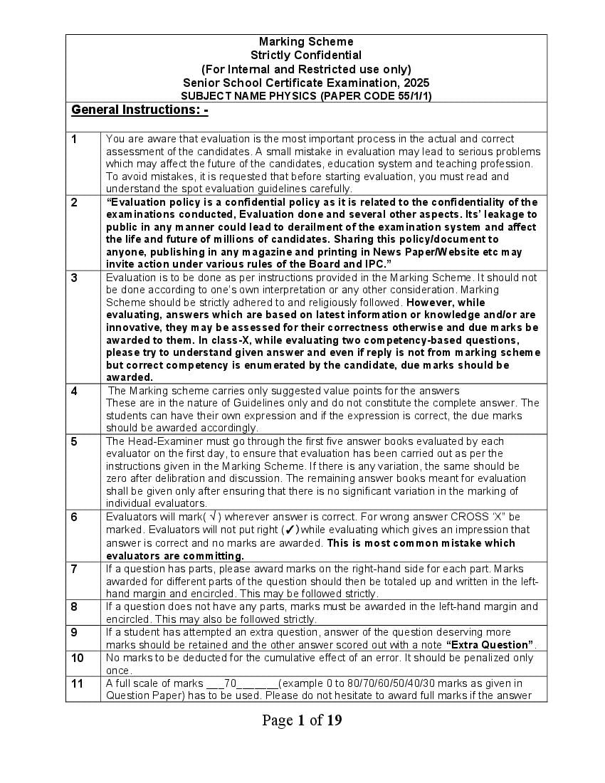
Page 1
Strictly Confidential
(For Internal and Restricted use only)
Senior School Certificate Examination, 2025
SUBJECT NAME PHYSICS (PAPER CODE 55/1/1)
General Instructions: -
1 You are aware that evaluation is the most important process in the actual and correct
assessment of the candidates. A small mistake in evaluation may lead to serious problems
which may affect the future of the candidates, education system and teaching profession.
To avoid mistakes, it is requested that before starting evaluation, you must read and
understand the spot evaluation guidelines carefully.
2 “Evaluation policy is a confidential policy as it is related to the confidentiality of the
examinations conducted, Evaluation done and several other aspects. Its’ leakage to
public in any manner could lead to derailment of the examination system and affect
the life and future of millions of candidates. Sharing this policy/document to
anyone, publishing in any magazine and printing in News Paper/Website etc may
invite action under various rules of the Board and IPC.”
3 Evaluation is to be done as per instructions provided in the Marking Scheme. It should not
be done according to one’s own interpretation or any other consideration. Marking
Scheme should be strictly adhered to and religiously followed. However, while
evaluating, answers which are based on latest information or knowledge and/or are
innovative, they may be assessed for their correctness otherwise and due marks be
awarded to them. In class-X, while evaluating two competency-based questions,
please try to understand given answer and even if reply is not from marking scheme
but correct competency is enumerated by the candidate, due marks should be
awarded.
4 The Marking scheme carries only suggested value points for the answers
These are in the nature of Guidelines only and do not constitute the complete answer. The
students can have their own expression and if the expression is correct, the due marks
should be awarded accordingly.
5 The Head-Examiner must go through the first five answer books evaluated by each
evaluator on the first day, to ensure that evaluation has been carried out as per the
instructions given in the Marking Scheme. If there is any variation, the same should be
zero after delibration and discussion. The remaining answer books meant for evaluation
shall be given only after ensuring that there is no significant variation in the marking of
individual evaluators.
6 Evaluators will mark( √ ) wherever answer is correct. For wrong answer CROSS ‘X” be
marked. Evaluators will not put right (✓)while evaluating which gives an impression that
answer is correct and no marks are awarded. This is most common mistake which
evaluators are committing.
7 If a question has parts, please award marks on the right-hand side for each part. Marks
awarded for different parts of the question should then be totaled up and written in the left-
hand margin and encircled. This may be followed strictly.
8 If a question does not have any parts, marks must be awarded in the left-hand margin and
encircled. This may also be followed strictly.
9 If a student has attempted an extra question, answer of the question deserving more
marks should be retained and the other answer scored out with a note “Extra Question”.
10 No marks to be deducted for the cumulative effect of an error. It should be penalized only
once.
11 A full scale of marks ___70_______(example 0 to 80/70/60/50/40/30 marks as given in
Question Paper) has to be used. Please do not hesitate to award full marks if the answer
Page 1 of 19
Page 2
12 Every examiner has to necessarily do evaluation work for full working hours i.e., 8 hours
every day and evaluate 20 answer books per day in main subjects and 25 answer books
per day in other subjects (Details are given in Spot Guidelines).This is in view of the
reduced syllabus and number of questions in question paper.
13 Ensure that you do not make the following common types of errors committed by the
Examiner in the past:-
● Leaving answer or part thereof unassessed in an answer book.
● Giving more marks for an answer than assigned to it.
● Wrong totaling of marks awarded on an answer.
● Wrong transfer of marks from the inside pages of the answer book to the title page.
● Wrong question wise totaling on the title page.
● Wrong totaling of marks of the two columns on the title page.
● Wrong grand total.
● Marks in words and figures not tallying/not same.
● Wrong transfer of marks from the answer book to online award list.
● Answers marked as correct, but marks not awarded. (Ensure that the right tick mark
is correctly and clearly indicated. It should merely be a line. Same is with the X for
incorrect answer.)
● Half or a part of answer marked correct and the rest as wrong, but no marks awarded.
14 While evaluating the answer books if the answer is found to be totally incorrect, it should
be marked as cross (X) and awarded zero (0)Marks.
15 Any un assessed portion, non-carrying over of marks to the title page, or totaling error
detected by the candidate shall damage the prestige of all the personnel engaged in the
evaluation work as also of the Board. Hence, in order to uphold the prestige of all
concerned, it is again reiterated that the instructions be followed meticulously and
judiciously.
16 The Examiners should acquaint themselves with the guidelines given in the “Guidelines
for spot Evaluation” before starting the actual evaluation.
17 Every Examiner shall also ensure that all the answers are evaluated, marks carried over to
the title page, correctly totaled and written in figures and words.
18 The candidates are entitled to obtain photocopy of the Answer Book on request on
payment of the prescribed processing fee. All Examiners/Additional Head Examiners/Head
Examiners are once again reminded that they must ensure that evaluation is carried out
strictly as per value points for each answer as given in the Marking Scheme.
Page 2 of 19
Page 3
Code: 55/1/1
Q.No VALUE POINTS/EXPECTED ANSWERS Marks Total
Marks
SECTION A
1 (A) q 2 q 3 q1 1 1
2 R 1 1
(C)
8
3 (B) ˆ ˆ μN
-3j+2k 1 1
4 (B) 0.30 C 1 1
5 (B) 2866 1 1
6 i0 v 0 1 1
(D) cos
2
7 (A) X- rays , Micro waves , UV radiation 1 1
8 3H 1 1
(B)
4
9 h 1 1
(C)
m
10 ( B) e p d 1 1
11 (A) 1 1
12 (C) The barrier height and the depletion layer width both decrease. 1 1
13 (A) Both Assertion (A) and Reason (R) are true and Reason (R) is the correct 1 1
explanation of Assertion( A).
14 (A) Both Assertion (A) and Reason (R) are true and Reason (R) is the correct explanation 1 1
of Assertion( A).
15 (C) Assertion (A) is true but Reason ( R) is false. 1 1
16 (D) Assertion (A) is false and Reason ( R) is also false. 1 1
SECTION - B
17
Calculating the value of E 1
Calculating the value of r 1
E V Ir
In first case ½
E = 5 + 2r
In second case
E = 4 + 4r ½
After solving
Page 3 of 19
Page 4
r = 0.5 Ω ½ 2
18 (a)
Calculating the width of the slit 2
Condition for Minima
a sinθ = nλ 1
For First Minima n=1
a sin 30° = 600 × 10-9 m ½
1
a× = 600 × 10-9 m
2
a = 1200 × 10-9 m
= 1.2 × 10⁻⁶ m ½
OR
(b) Finding the Intensity 2
2
Phase difference = × path difference ½
2
x
x given
8
2
8
½
4
I I I 2 I I cos ½
4
1
= 2I 2I
2
1
I 2I 1
2
= I (2 2 )
I = 3.414 I ½
Alternatively
2
Phase difference = × path difference ½
Page 4 of 19
Page 5
x
x given
8
2
8 ½
4
½
I 4I cos 2
2
½ 2
I 4I cos 2
8
19
Calculating angle θ 2
For critical Angle
n2 1 ½
n1 sin c
2
n1=1 n2= (given)
3
2 1
3 sin c
3
sin c
2
c 60
r 90 c
= 30° ½
From Snell’s law at air rod interface
n1 sin i n 2 sin r ½
Page 5 of 19
Page 6
n2
sin r
2 sin
3 sin 30
0
2 1
sin
3 2
1
sin
3
1
sin 1 ½ 2
3
20 Proving Time period of Revolution ,T α n3 2
2πr ½
T= ---------- (1)
v
From Bohr’s quantization condition
nh
mvr=
2π
nh
v= ---------- (2) ½
2πmr
From (1) and (2)
2πr
T=
nh
2πmr
2πr(2πmr)
T=
nh
4π mr 2
2
½
T=
nh
n2 h 2
From r=
4π2mke2
4π2m n2h2
2
T=
nh 4π2mke2
n 3 h3
T=
4π2 mk 2e 4
T n3 ½
Alternatively ---
Page 6 of 19
Page 7
T=
v
r n2 ½
1
and v ½
n
T n3 ½ 2
21
Finding the number of holes 1
One example 1
1 dopant atom for 5×10⁷ Si atoms
atoms
and number density of Si atoms = 5×1028 (given )
m3
5 1028
No. of holes created per m3 = 1021 1
5 10 7
Number of holes created per cubic centimeter
1021
= 1015
10 6
Any one example of dopant - Aluminium / Indium / Gallium 1
2
SECTION - C
22 (a)
Finding
(i) Equivalent emf of combination 1
(ii) Equivalent internal resistance of combination 1
(iii) Current drawn from combination 1
E1r2 E 2r1 ½
(i) Because Eeq
r1 r2
3 0.4 6 0.2
Eeq = 4V ½
0.6
r1r2 ½
(ii) req
r1 r2
0.2 0.4 ½
req 0.133
0.2 0.4
E
(iii) I ½
R req
4 4
I A
4 0.13 4.13 ½
I 0.9A
Page 7 of 19
Page 8
(b)
(i) Finding the relation
(i) between and R 1
(ii) between and vd 1
(ii) To identify whether all free electrons are moving in the same
direction. 1
(i) l 2l
Al Al = volume of the wire
Al A (2l )
A
A
2
l
R= ½
A
l
R
A
(2l )
R
A
2
R ½
4
R
Alternatively
R n 2R ½
n= 2
R 4R ½
eE
(ii) v d = ½
m
eV
vd =
ml
eV
v d =
ml
v d l 1 ½
vd l 2
(ii) No 1 3
23
Derivation for
Magnetic field on the axis 2½
Magnetic field at the centre ½
Page 8 of 19
Page 9
From Biot Savart’ s Law
I dl r
½
dB
4 r3
Now r2 = x2 + R2
Because dl r rdl
idl
∴ dB
4 (x R 2 )
2 ½
dB has two components.
All the components perpendicular to x- axis are summed over and we obtain a null result.
Only x- components contribute. The net contribution along x- direction
dB x dB cos ½
R
cos
R 2 x 2 2
1
Thus :
i R
dB x dl
4
R 2 x 2 2
3
Summing dB x over the entire loop
=2
iR 2 ½
B B x iˆ iˆ
3
2(x 2 R ) 2 2
Magnetic field at the centre of the loop-
Here x= 0
i
B iˆ
2R ½ 3
Page 9 of 19
Page 10
a) Deriving the expression for energy stored in an inductor. 1½
b) Deriving the energy density of magnetic field. 1½
a) Induced emf in an inductor
dI
L ½
dt
Rate of work done at any instant
dW
I ½
dt
Total Amount of work done in establishing current I
W = dW LIdI
I
0
Energy required to build up current I is
W = ½ L I2 ½
b) The Magnetic Energy is
W= UB = ½ LI2
B
2
=½L as B= n μ0I ½
n 0
Using L= 0n 2 Al
1 B2
UB = 0n 2 Al 2 2
2 0 n ½
UB
Energy density =
volume
UB 1 B2 1
= ×μ 0 n 2 A l 2 2 ×
volume 2 μ 0 n Al
1 B2
= ½ 3
2 μ0
25
a) Showing that ( Ic + Id ) has the same value. 2
b) Explanation of Kirchhoff’s first rule at each plate of capacitor. 1
a) Total current I = Ic + Id
outside the capacitor
Id =0 ½
∴ I = Ic
Inside the capacitor
Ic = 0 ½
Page 10 of 19
Page 11
∴ I = Id = 0 ½
dt
EA
d
= 0
dt
d
= 0 A
dt 0
0 d Q
= A
0 dt A ½
dQ
I = = Ic
dt
Alternatively
Total current I = Ic + Id
outside the capacitor
Id =0 ½
∴ I = Ic
Inside the capacitor ½
Ic = 0
I = Id = 0 dE
dt ½
= 0 d Q
dt 0
½
dQ
I= =Ic
dt
hence Ic + Id has the same value at all points of the circuit.
b) Yes 1
Current entering the capacitor is (Ic) and between the plates capacitor is (Id )
Ic =Id
which validates Kirchhoff’s junction rule. 3
26
Reason for
a) All photoelectrons not having same Kinetic Energy. 1
b) Having different saturation current for different intensity. 1
c) Stopping of emission of photoelectrons at a certain wavelength. 1
a) When monochromatic light is incident on a metal surface then more/less tightly bound 1
electrons will emerge with less/more kinetic energy. So all the photoelectrons do not eject
with same kinetic energy.
b) Maximum number of photoelectrons ejected per second (saturation current) is directly
proportional to the Intensity of incident radiation Hence saturation current is different for 1
different intensities.
Page 11 of 19
Page 12
When λ> λ0, ν< ν0 ( threshold frequency) , no photoelectron is ejected. Emission of
photoelectrons stop at λ> λ0. 1 3
27
a) Defining Mass Defect ½
Defining Binding Energy ½
Describing Fission Process ½
b) Calculation of Mass Defect 1
Calculation of Energy ½
a) Difference in the mass of the nucleus and its constituents is defined as mass defect. ½
Binding Energy is the energy required to separate the nucleons from the nucleus. ½
In Fission process a heavy nucleus splits into lighter nuclei and energy is released. As a
result the Binding Energy per nucleon increases. ½
b) ∆m = (mp + mn) - md ½
∆m = ( 1.007277 + 1.008665) – 2.013553
∆m = 0.002389 u ½
Energy released = ∆m × c2
Energy released = 0.002389 × 931.5
= 2.2253 MeV ≈2.22 MeV ½
3
28
a) Circuit Arrangement for studying V–I characteristics. 1
b) Showing the shape of characteristic curves. 1
c) Two informations from the characteristics ½+½
a)
½
Circuit diagram for forward characteristics
Page 12 of 19
Page 13
Circuit diagram for Reverse characteristics
b)
1
Note : Please do not deduct marks for not writing values. ½+½
c) Any two informations
Knee voltage / reverse saturation current / Breakdown voltage / very low resistance in 3
forward biasing / very high resistance in Reverse biasing.
SECTION - D
29 i) (B) 5mC 1
ii) (A) zero 1
iii) (D) [ M0L0TA0] 1
1
iv) (A) mA
2 e
Note: 1 mark for this part may be given to all the students who have attempted other
parts of the question.
OR
(B) 0.5 mA 1 4
30 i) ( C) 1
ii) ( A) For a convex mirror magnification is always negative 1
iii) ( B ) 2f 1
Page 13 of 19
Page 14
( B) 12 cm
iv) ( C ) X 1X 2 1 4
SECTION - E
31 a) i) Calculating the change in electrostatic energy of the system 2
ii) (1) Finding the capacitance. 1
(2) Finding the potential difference. 1
(3) Answering and Reason ½+½
3 105
(i) E rˆ ( Given) dV E .dr
r 2
V = 3 × 10⁵ / r
Electrostatic energy of the system in the absence of the field
Kq1q 2
Ui = ½
r12
Electrostatic energy in the presence of the field
Kq1q 2
Uf = q1V (r1 ) q 2V (r2 )
r12
½
∆U = Uf - Ui = q1V (r1 ) q 2V (r2 )
5 10 6 3 105 1 10 6 3 105 ½
∆U =
3 10 2 3 102
= 40 J ½
Q 80
ii) 1) C = = 5μF 1
V 16
2) C KC
½
= 3×5μF = 15 μF
Q 80μC
V = = =5.33V ½
C 15μF
3) No, ½
The capacitance of the system depends on its geometry. ½
OR
b) i) Comparing the magnitude of the Electric fields 2
ii) Calculating the work done on the charge 3
Total charge for A = Total charge for B = Total charge for C = +4q 1
kQ
As , E = 2
r
Page 14 of 19
Page 15
k(4q ) 4kq ½
E=
9R 2 9R 2
∴ E A = EB = Ec ½
k 6 106 k 6 10 6
ii) Vc = 1
5 10 5 10 2
2
= 0
k 6 106 k 6 106
VA
15 10
2
5 102 ½
k 6 106 1 3
= 15
102
9 109 6 106 2
=
15 10 2
= - 7.2 ×10⁵ V ½
W = q V A Vc ½
= 5 10 6 7.2 105 0
W = - 3.6 J ½
5
32 a)
i) Finding the direction of magnetic field near points P,Q and R ½ + ½ + ½
Conclusion about the relative magnitude of magnetic field. ½+½+½
ii) Showing the given expression of magnetic moment. 2
i) Near point P
Magnetic field is acting into the plane of the paper as Force is acting upwards. ½
Near point Q
Magnetic field is into the plane of paper as force is acting upwards. ½
Near point R
Magnetic field is acting out of the plane of the paper as F is acting downwards. ½
Relative Magnitude of the Magnetic field.
1
As B
r
Therefore,
Near point P, magnitude of B is small. ½
Near point Q, B is relatively smaller than point P. ½
Near point R, B is relatively larger than point P. ½
(BQ< BP<BR)
ii) Let r be the radius of the circular coil and I is the current in the coil then
Page 15 of 19
Page 16
B or I
2r 0
A ½
A = πr2 r=
M = IA ½
2Br
= A
0
2BA A ½
=
0
OR
b)
i) Deriving the expression for the torque. 3
ii) 1) Finding the change in radius. 1
2) Finding the change in time period of Revolution. 1
i)
½
F1 and F2 are the forces acting on two arms of the rectangular coil having sides a and b.
F1 F2 I b B ( b = length of the arm)
1
Forces constitute a couple. The magnitude of Torque on the loop is –
a a
F1 sin F2 sin
2 2
½
a b B sin
B sin ½
IA B
½
Page 16 of 19
Page 17
½
If the plane of the current carrying coil marks an angle ∝ with the magnetic field
FDA FBc (cancel each other) .
½
Force on the arm DC is into the plane of the paper
FDC IbB . ½
Force on the arm AB is out of the plane of the paper.
FAB IbB ½
Both of them form a couple and Torque acting on the coil is
τ=either force ×perpendicular distance between the two forces.
IbB a cos
= IabB cos
IAB cos ½
Let n̂ =outward drawn normal to the plane of the coil.
900
900
IAB cos(90 )
IAB sin ½
IA B
mv 2mK ½
ii) 1) r= =
qB qB
r α K
r K/2 1
= =
r K 2
r ½
r=
2
Page 17 of 19
Page 18
2) T= ½
qB
Time period does not depend on Kinetic Energy
∴ Time period will not change. ½ 5
33 a)
i) 1) Definition of coherent sources. 1
Necessity of coherent sources for sustained interference pattern 1
2) Explanation 1
ii) 1) Finding distance between adjacent bright fringes. 1
2) Finding angular width 1
i) 1) If the phase difference between the displacement produced by each of the wave
from two sources does not change with time then two sources are said to be coherent. 1
Alternatively
Two sources are said to be coherent if they emit light continuously of same frequency /
wavelength and having zero or constant phase difference.
Coherent sources are required to get constant phase difference. 1
2) Two independent sources will never be coherent because phase difference between
them will not be constant. 1
ii) 1) Distance between adjacent bright fringe = fringe width
D
½
d
600 109 1.2
7.2 mm ½
0.1 10 3
2) ½
d
600 109
= 6×10⁻³ rad= 0.34° ½
0.1 103
Give full marks if the student writes the answer in radians only.
OR
b)
i) Definition of wave front. 1
Drawing the incident and refracted wave front ½ +½
ii) Drawing the ray diagram 1
Obtaining the position of final image 2
i) A wavefront is a locus of all the points which oscillate in phase.
1
½+½
Page 18 of 19
Page 19
1
From Ist surface , Refraction is from rarer to denser medium and object is at ∞
n1 =1 , n2 =1.5, R = 15 cm , u= ∞
n2 n1 n2 -n1
- = ½
v u R
1.5 1 1.5 1
v 15 ½
v= 45 cm
From 2nd surface , Refraction is from denser to rarer medium and object is at 15 cm
n1 =1 , n2 =1.5, R = -15 cm , u= 15cm
n1 n2 n1-n2 ½
- =
v u R
1 1.5 1 1.5
v 15 15
v= 7.5 cm ½ 5
Page 19 of 19
Page 20
Strictly Confidential
(For Internal and Restricted use only)
Senior School Certificate Examination, 2025
SUBJECT NAME PHYSICS (PAPER CODE 55/1/2)
General Instructions: -
1 You are aware that evaluation is the most important process in the actual and correct
assessment of the candidates. A small mistake in evaluation may lead to serious problems
which may affect the future of the candidates, education system and teaching profession.
To avoid mistakes, it is requested that before starting evaluation, you must read and
understand the spot evaluation guidelines carefully.
2 “Evaluation policy is a confidential policy as it is related to the confidentiality of the
examinations conducted, Evaluation done and several other aspects. Its’ leakage to
public in any manner could lead to derailment of the examination system and affect
the life and future of millions of candidates. Sharing this policy/document to
anyone, publishing in any magazine and printing in News Paper/Website etc may
invite action under various rules of the Board and IPC.”
3 Evaluation is to be done as per instructions provided in the Marking Scheme. It should not
be done according to one’s own interpretation or any other consideration. Marking
Scheme should be strictly adhered to and religiously followed. However, while
evaluating, answers which are based on latest information or knowledge and/or are
innovative, they may be assessed for their correctness otherwise and due marks be
awarded to them. In class-X, while evaluating two competency-based questions,
please try to understand given answer and even if reply is not from marking scheme
but correct competency is enumerated by the candidate, due marks should be
awarded.
4 The Marking scheme carries only suggested value points for the answers
These are in the nature of Guidelines only and do not constitute the complete answer. The
students can have their own expression and if the expression is correct, the due marks
should be awarded accordingly.
5 The Head-Examiner must go through the first five answer books evaluated by each
evaluator on the first day, to ensure that evaluation has been carried out as per the
instructions given in the Marking Scheme. If there is any variation, the same should be
zero after delibration and discussion. The remaining answer books meant for evaluation
shall be given only after ensuring that there is no significant variation in the marking of
individual evaluators.
6 Evaluators will mark( √ ) wherever answer is correct. For wrong answer CROSS ‘X” be
marked. Evaluators will not put right (✓)while evaluating which gives an impression that
answer is correct and no marks are awarded. This is most common mistake which
evaluators are committing.
7 If a question has parts, please award marks on the right-hand side for each part. Marks
awarded for different parts of the question should then be totaled up and written in the left-
hand margin and encircled. This may be followed strictly.
8 If a question does not have any parts, marks must be awarded in the left-hand margin and
encircled. This may also be followed strictly.
9 If a student has attempted an extra question, answer of the question deserving more
marks should be retained and the other answer scored out with a note “Extra Question”.
10 No marks to be deducted for the cumulative effect of an error. It should be penalized only
once.
11 A full scale of marks ___70_______(example 0 to 80/70/60/50/40/30 marks as given in
Question Paper) has to be used. Please do not hesitate to award full marks if the answer
Page 1 of 18
Page 21
12 Every examiner has to necessarily do evaluation work for full working hours i.e., 8 hours
every day and evaluate 20 answer books per day in main subjects and 25 answer books
per day in other subjects (Details are given in Spot Guidelines).This is in view of the
reduced syllabus and number of questions in question paper.
13 Ensure that you do not make the following common types of errors committed by the
Examiner in the past:-
● Leaving answer or part thereof unassessed in an answer book.
● Giving more marks for an answer than assigned to it.
● Wrong totaling of marks awarded on an answer.
● Wrong transfer of marks from the inside pages of the answer book to the title page.
● Wrong question wise totaling on the title page.
● Wrong totaling of marks of the two columns on the title page.
● Wrong grand total.
● Marks in words and figures not tallying/not same.
● Wrong transfer of marks from the answer book to online award list.
● Answers marked as correct, but marks not awarded. (Ensure that the right tick mark
is correctly and clearly indicated. It should merely be a line. Same is with the X for
incorrect answer.)
● Half or a part of answer marked correct and the rest as wrong, but no marks awarded.
14 While evaluating the answer books if the answer is found to be totally incorrect, it should
be marked as cross (X) and awarded zero (0)Marks.
15 Any un assessed portion, non-carrying over of marks to the title page, or totaling error
detected by the candidate shall damage the prestige of all the personnel engaged in the
evaluation work as also of the Board. Hence, in order to uphold the prestige of all
concerned, it is again reiterated that the instructions be followed meticulously and
judiciously.
16 The Examiners should acquaint themselves with the guidelines given in the “Guidelines
for spot Evaluation” before starting the actual evaluation.
17 Every Examiner shall also ensure that all the answers are evaluated, marks carried over to
the title page, correctly totaled and written in figures and words.
18 The candidates are entitled to obtain photocopy of the Answer Book on request on
payment of the prescribed processing fee. All Examiners/Additional Head Examiners/Head
Examiners are once again reminded that they must ensure that evaluation is carried out
strictly as per value points for each answer as given in the Marking Scheme.
Page 2 of 18
Page 22
Code: 55/1/2
Q.No. VALUE POINTS/EXPECTED ANSWERS Marks Total
Marks
SECTION A
1 (C) C 1 1
2 (B) Using a wire of same radius and half length. 1 1
3
ˆ ˆ μN
(B) -3j+2k 1 1
4 (C) 2 1 1
5 (B) 2866 1 1
6 i0 v 0 1 1
(D) cos
2
7 (B) Speed Wavelength Frequency 1 1
Remains same Decreases Increases
8 v 1 1
(A) medium ‘1’ and at an angle greater that sin-1 1
v2
9 (A) 10 16
1 1
10 (A) 1 1
11 (C) The barrier height and the depletion layer width both decrease. 1 1
12 ( B) e p d 1 1
13 (D) Assertion (A) is false and Reason ( R) is also false. 1 1
14 (C) Assertion (A) is true but Reason ( R) is false. 1 1
15 (A) Both Assertion (A) and Reason (R) are true and Reason (R) is the correct 1 1
explanation of Assertion( A).
16 A) Both Assertion (A) and Reason (R) are true and Reason (R) is the correct 1 1
explanation of Assertion( A).
SECTION - B
17
Obtaining Ohm’s law from 1½
Writing the condition ½
E j
V I ½
l A ½
Page 3 of 18
Page 23
= constant (Ohm’s Law) ½
I A
Condition for non- validity of Ohm’s Law
High temperature / in semiconductor ½ 2
18 (a)
Calculating the width of the slit 2
Condition for Minima
a sinθ = nλ 1
For First Minima n=1
a sin 30° = 600 × 10-9 m ½
1
a× = 600 × 10-9 m
2
a = 1200 × 10-9 m
= 1.2 × 10⁻⁶ m ½
OR
(b) Finding the Intensity 2
2
Phase difference = × path difference ½
2
x
x given
8
2
8
½
4
I I I 2 I I cos ½
4
1
= 2I 2I
2
1
I 2I 1
2
= I (2 2 )
I = 3.414 I ½
Alternatively
Page 4 of 18
Page 24
Phase difference = × path difference
½
2
x
x given
8
2
8
½
4
I 4I cos 2 ½
2
½ 2
I 4I cos 2
8
19
Finding the position 1½
Nature of the Image formed ½
Refraction from rarer to denser medium
n1 n 2 n 2 -n1 ½
+ =
-u v R
R
u=- , n1 =1,n2 =1.5
2
2 1.5 1.5-1 ½
+ =
R v R
1.5 0.5 2
= -
v R R
1.5 1.5
=-
v R
v=-R ½
The image is virtual in air at distance R. ½ 2
20
Finding the Angular momentum 2
13.6
En eV ½
n2
13.6
n2 = 4
3.4
½
n=2
Angular momentum
Page 5 of 18
Page 25
L=
2 ½
h 6.63 1034
L= = 2.11 ×10⁻³⁴ Js ½ 2
3.14
21
Finding the number of holes 1
One example 1
1 dopant atom for 5×10⁷ Si atoms
atoms
and number density of Si atoms = 5×1028 (given )
m3
5 1028
No. of holes created per m3 = 1021
5 10 7
1
Number of holes created per cubic centimeter
1021
= 1015
10 6
Any one example of dopant - Aluminium / Indium / Gallium
1 2
SECTION - C
22 (a)
Finding
(i) Equivalent emf of combination 1
(ii) Equivalent internal resistance of combination 1
(iii) Current drawn from combination 1
E1r2 E 2r1
(i) Because Eeq ½
r1 r2
3 0.4 6 0.2
Eeq = 4V
0.6 ½
rr
(ii) req 1 2
r1 r2 ½
0.2 0.4
req 0.133 ½
0.2 0.4
E
(iii) I ½
R req
4 4 ½
I A
4 0.13 4.13
I 0.9A
OR
Page 6 of 18
Page 26
(i) Finding the relation
(i) between and R 1
(ii) between and vd 1
(ii) To identify whether all free electrons are moving in the same
direction. 1
(i) l 2l
Al Al = volume of the wire
Al A (2l )
A
A ½
2
l
R=
A
l
R
A
(2l )
R
A
2 ½
R
4
R
Alternatively ½
R n 2R
n= 2 ½
R 4R
eE ½
(ii) v d =
m
eV
vd =
ml
eV
v d =
ml
vd l 1 ½
vd l 2
1 3
(ii) No
23 a) Defining magnetic moment 1
SI unit of magnetic moment ½
b) Finding the magnitude of magnetic field 1½
a) Magnetic moment of a current carrying coil is defined as the product of 1
Page 7 of 18
Page 27
Alternatively
M IA
S.I. unit is Am2 ½
b) NIABsinθ
1 0.12=60×2×1.5×10-3 ×Bsinθ
2
Bsinθ ½
3
2 0.05 60 2 1.5 10 3 Bcosθ
5
Bcosθ= ½
18
B= B2sin2θ+B2cos2θ
2 5 13
2 2
= = T ½ 3
3 18 18
24
Deriving the expression for mutual Inductance 2
Showing M21 = M12 1
½
Let N1 and N2 be the total number of turns of coils S 1 and S2 respectively.
When current I2 is set up in S2, flux linkage with solenoid S1 is –
N11 M12I2 --(i) ½
N11 n1l πr12 μ 0 n2I2
N11 μ 0 n1n2πr12l I2 --(ii) ½
From (i) and (ii)
M12= μ 0 n1n2πr12l ½
Page 8 of 18
Page 28
is –
N22 M21I1 --(iii)
N22 = n2l πr12 μ 0 n1I1
½
--(iv)
From (iii) and (iv)
M21 =n1n2πr12l
M 12 M 21
½ 3
25 a) Showing that ( Ic + Id ) has the same value. 2
b) Explanation of Kirchhoff’s first rule at each plate of capacitor. 1
a) Total current I = Ic + Id
outside the capacitor
Id =0 ½
∴ I = Ic
Inside the capacitor
Ic = 0 ½
d
∴ I = Id = 0 E
dt
EA
d
= 0 ½
dt
d
= 0 A
dt 0
0 d Q
= A
0 dt A
dQ
I = = Ic
dt ½
Alternatively
Total current I = Ic + Id
outside the capacitor
Id =0 ½
∴ I = Ic
Inside the capacitor
Ic = 0 ½
I = Id = 0 dE
dt ½
= 0 d Q
dt 0
dQ ½
I= =Ic
dt
hence Ic + Id has the same value at all points of the circuit.
Page 9 of 18
Page 29
Current entering the capacitor is (Ic) and between the plates capacitor is (Id )
Ic =Id
which validates Kirchhoff’s junction rule. 3
26
a) Drawing a plot of frequency(ν) as a function of stopping potential (V0) 1
Obtaining information from intercept ½
b) Calculating
i) the momentum 1
ii) de Broglie wavelength ½
a)
1
Value of work function can be obtained from intercept.
½
b) i) p= 2mK
= 2 9.1 1031 80 1.6 1019 ½
= 4.8 ×10⁻²⁴kg m/s
h 6.63×10⁻³⁴ ½
ii) λ= = =1.38×10⁻⁹m
p 4.8×10⁻²⁵
½ 3
27
a) Circuit Arrangement for studying V–I characteristics. 1
b) Showing the shape of characteristic curves. 1
c) Two informations from the characteristics ½+½
a)
½
Circuit diagram for forward characteristics
Page 10 of 18
Page 30
Circuit diagram for Reverse characteristics
b)
1
Note : Please do not deduct marks for not writing values.
c) Any two informations
Knee voltage / reverse saturation current / Breakdown voltage / very low ½+½
resistance in forward biasing / very high resistance in Reverse biasing. 3
28
a) Defining Mass Defect ½
Defining Binding Energy ½
Describing Fission Process ½
b) Calculation of Mass Defect 1
Calculation of Energy ½
a) Difference in the mass of the nucleus and its constituents is defined as mass
defect. ½
Binding Energy is the energy required to separate the nucleons from the ½
nucleus.
In Fission process a heavy nucleus splits into lighter nuclei and energy is ½
released. As a result the Binding Energy per nucleon increases.
Page 11 of 18
Page 31
∆m = ( 1.007277 + 1.008665) – 2.013553
∆m = 0.002389 u ½
Energy released = ∆m × c2
Energy released = 0.002389 × 931.5
= 2.2253 MeV ≈2.22 MeV ½ 3
SECTION - D
29 i) ( C) 1
ii) ( A) For a convex mirror magnification is always negative 1
iii) ( B ) 2f 1
OR
( B) 12 cm
iv) ( C ) X 1X 2 1 4
30 i) (B) 5mC 1
ii) (A) zero 1
iii) (D) [ M0L0TA0] 1
1
iv) (A) mA
2 e
Note: 1 mark for this part may be given to all the students who have
attempted other parts of the question.
OR
(B) 0.5 mA 1 4
SECTION - E
31 a)
i) 1) Definition of coherent sources. 1
Necessity of coherent sources for sustained interference pattern 1
2) Explanation 1
ii) 1) Finding distance between adjacent bright fringes. 1
2) Finding angular width 1
i) 1) If the phase difference between the displacement produced by each of the
wave from two sources does not change with time then two sources are said to 1
be coherent.
Alternatively
Two sources are said to be coherent if they emit light continuously of same
frequency / wavelength and having zero or constant phase difference.
Coherent sources are required to get constant phase difference. 1
2) Two independent sources will never be coherent because phase difference
between them will not be constant. 1
ii) 1) Distance between adjacent bright fringe = fringe width
Page 12 of 18
Page 32
d
600 109 1.2
7.2 mm ½
0.1 10 3
2) ½
d
600 109
= 6×10⁻³ rad= 0.34° ½
0.1 10 3
Give full marks if the student writes the answer in radians only.
OR
b)
i) Definition of wave front. 1
Drawing the incident and refracted wave front ½ +½
ii) Drawing the ray diagram 1
Obtaining the position of final image 2
i) A wavefront is a locus of all the points which oscillate in phase.
1
½+½
ii)
1
From Ist surface , Refraction is from rarer to denser medium and object is at ∞
n1 =1 , n2 =1.5, R = 15 cm , u= ∞
n2 n1 n2 -n1 ½
- =
v u R
Page 13 of 18
Page 33
v 15
v= 45 cm ½
From 2nd surface , Refraction is from denser to rarer medium and object is at 15
cm
n1 =1 , n2 =1.5, R = -15 cm , u= 15cm
n1 n2 n1-n2 ½
- =
v u R
1 1.5 1 1.5
v 15 15 ½ 5
v= 7.5 cm
32 a)
i) Calculating the change in electrostatic energy of the system 2
ii) (1) Finding the capacitance. 1
(2) Finding the potential difference. 1
(3) Answering and Reason ½+½
3 105
(i) E rˆ ( Given) dV E .dr
r2
V = 3 × 10⁵ / r
Electrostatic energy of the system in the absence of the field
Kq1q 2
Ui = ½
r12
Electrostatic energy in the presence of the field
Kq1q 2
Uf = q1V (r1 ) q 2V (r2 )
r12
½
∆U = Uf - Ui = q1V (r1 ) q 2V (r2 )
5 10 6 3 105 1 10 6 3 105 ½
∆U =
3 10 2 3 102
= 40 J ½
Q 80
ii) 1) C = = 5μF 1
V 16
2) C KC
½
= 3×5μF = 15 μF
Q 80μC
V = = =5.33V ½
C 15μF
3) No, ½
The capacitance of the system depends on its geometry. ½
OR
Page 14 of 18
Page 34
i) Comparing the magnitude of the Electric fields 2
ii) Calculating the work done on the charge 3
Total charge for A = Total charge for B = Total charge for C = +4q 1
kQ
As , E = 2
r
Since Q = 4q and r = 3R
k(4q ) 4kq ½
E=
9R 2 9R 2 ½
∴ E A = EB = Ec
k 6 106 k 6 10 6 1
ii) Vc =
5 10 5 10 2
2
= 0
k 6 106 k 6 106
VA ½
15 10
2
5 102
k 6 106 1 3
= 15
102
9 109 6 106 2
=
15 10 2
= - 7.2 ×10⁵ V ½
W = q V A Vc ½
= 5 10 6 7.2 105 0
W = - 3.6 J ½ 5
33 a)
i) Finding the direction of magnetic field near points P,Q and R ½ + ½ + ½
Conclusion about the relative magnitude of magnetic field. ½+½+½
ii) Showing the given expression of magnetic moment. 2
i) Near point P
Magnetic field is acting into the plane of the paper as Force is acting upwards. ½
Near point Q
Magnetic field is into the plane of paper as force is acting upwards. ½
Near point R
Magnetic field is acting out of the plane of the paper as F is acting downwards. ½
Relative Magnitude of the Magnetic field.
1
As B
r
Therefore,
Near point P, magnitude of B is small. ½
Near point Q, B is relatively smaller than point P. ½
Page 15 of 18
Page 35
(BQ< BP<BR)
ii) Let r be the radius of the circular coil and I is the current in the coil then
I 2Br
B 0 or I ½
2r 0
A ½
A = πr2 r=
M = IA ½
2Br
= A
0
2BA A ½
=
0
OR
b)
i) Deriving the expression for the torque. 3
ii) 1) Finding the change in radius. 1
2) Finding the change in time period of Revolution. 1
i)
½
F1 and F2 are the forces acting on two arms of the rectangular coil having sides
a and b.
1
F1 F2 I b B ( b = length of the arm)
Forces constitute a couple. The magnitude of Torque on the loop is –
a a
F1 sin F2 sin ½
2 2
a b B sin
½
B sin
IA B ½
Page 16 of 18
Page 36
½
If the plane of the current carrying coil marks an angle ∝ with the magnetic field
FDA FBc (cancel each other) .
½
Force on the arm DC is into the plane of the paper
FDC IbB . ½
Force on the arm AB is out of the plane of the paper.
½
FAB IbB
Both of them form a couple and Torque acting on the coil is
τ=either force ×perpendicular distance between the two forces.
IbB a cos
= IabB cos
IAB cos ½
Let n̂ =outward drawn normal to the plane of the coil.
900
900
IAB cos(90 )
IAB sin ½
IA B
mv 2mK ½
ii) 1) r= =
qB qB
r α K
r K/2 1
= =
r K 2
r
r= ½
2
Page 17 of 18
Page 37
2) T= ½
qB
Time period does not depend on Kinetic Energy
∴ Time period will not change. ½
5
Page 18 of 18
Page 38
Strictly Confidential
(For Internal and Restricted use only)
Senior School Certificate Examination, 2025
SUBJECT NAME PHYSICS (PAPER CODE 55/1/3)
General Instructions: -
1 You are aware that evaluation is the most important process in the actual and correct
assessment of the candidates. A small mistake in evaluation may lead to serious problems
which may affect the future of the candidates, education system and teaching profession.
To avoid mistakes, it is requested that before starting evaluation, you must read and
understand the spot evaluation guidelines carefully.
2 “Evaluation policy is a confidential policy as it is related to the confidentiality of the
examinations conducted, Evaluation done and several other aspects. Its’ leakage to
public in any manner could lead to derailment of the examination system and affect
the life and future of millions of candidates. Sharing this policy/document to
anyone, publishing in any magazine and printing in News Paper/Website etc may
invite action under various rules of the Board and IPC.”
3 Evaluation is to be done as per instructions provided in the Marking Scheme. It should not
be done according to one’s own interpretation or any other consideration. Marking
Scheme should be strictly adhered to and religiously followed. However, while
evaluating, answers which are based on latest information or knowledge and/or are
innovative, they may be assessed for their correctness otherwise and due marks be
awarded to them. In class-X, while evaluating two competency-based questions,
please try to understand given answer and even if reply is not from marking scheme
but correct competency is enumerated by the candidate, due marks should be
awarded.
4 The Marking scheme carries only suggested value points for the answers
These are in the nature of Guidelines only and do not constitute the complete answer. The
students can have their own expression and if the expression is correct, the due marks
should be awarded accordingly.
5 The Head-Examiner must go through the first five answer books evaluated by each
evaluator on the first day, to ensure that evaluation has been carried out as per the
instructions given in the Marking Scheme. If there is any variation, the same should be
zero after delibration and discussion. The remaining answer books meant for evaluation
shall be given only after ensuring that there is no significant variation in the marking of
individual evaluators.
6 Evaluators will mark( √ ) wherever answer is correct. For wrong answer CROSS ‘X” be
marked. Evaluators will not put right (✓)while evaluating which gives an impression that
answer is correct and no marks are awarded. This is most common mistake which
evaluators are committing.
7 If a question has parts, please award marks on the right-hand side for each part. Marks
awarded for different parts of the question should then be totaled up and written in the left-
hand margin and encircled. This may be followed strictly.
8 If a question does not have any parts, marks must be awarded in the left-hand margin and
encircled. This may also be followed strictly.
9 If a student has attempted an extra question, answer of the question deserving more
marks should be retained and the other answer scored out with a note “Extra Question”.
10 No marks to be deducted for the cumulative effect of an error. It should be penalized only
once.
11 A full scale of marks ___70_______(example 0 to 80/70/60/50/40/30 marks as given in
Question Paper) has to be used. Please do not hesitate to award full marks if the answer
Page 1 of 18
Page 39
12 Every examiner has to necessarily do evaluation work for full working hours i.e., 8 hours
every day and evaluate 20 answer books per day in main subjects and 25 answer books
per day in other subjects (Details are given in Spot Guidelines).This is in view of the
reduced syllabus and number of questions in question paper.
13 Ensure that you do not make the following common types of errors committed by the
Examiner in the past:-
● Leaving answer or part thereof unassessed in an answer book.
● Giving more marks for an answer than assigned to it.
● Wrong totaling of marks awarded on an answer.
● Wrong transfer of marks from the inside pages of the answer book to the title page.
● Wrong question wise totaling on the title page.
● Wrong totaling of marks of the two columns on the title page.
● Wrong grand total.
● Marks in words and figures not tallying/not same.
● Wrong transfer of marks from the answer book to online award list.
● Answers marked as correct, but marks not awarded. (Ensure that the right tick mark
is correctly and clearly indicated. It should merely be a line. Same is with the X for
incorrect answer.)
● Half or a part of answer marked correct and the rest as wrong, but no marks awarded.
14 While evaluating the answer books if the answer is found to be totally incorrect, it should
be marked as cross (X) and awarded zero (0)Marks.
15 Any un assessed portion, non-carrying over of marks to the title page, or totaling error
detected by the candidate shall damage the prestige of all the personnel engaged in the
evaluation work as also of the Board. Hence, in order to uphold the prestige of all
concerned, it is again reiterated that the instructions be followed meticulously and
judiciously.
16 The Examiners should acquaint themselves with the guidelines given in the “Guidelines
for spot Evaluation” before starting the actual evaluation.
17 Every Examiner shall also ensure that all the answers are evaluated, marks carried over to
the title page, correctly totaled and written in figures and words.
18 The candidates are entitled to obtain photocopy of the Answer Book on request on
payment of the prescribed processing fee. All Examiners/Additional Head Examiners/Head
Examiners are once again reminded that they must ensure that evaluation is carried out
strictly as per value points for each answer as given in the Marking Scheme.
Page 2 of 18
Page 40
Code: 55/1/3
Q.No. VALUE POINTS/EXPECTED ANSWERS Marks Total
Marks
SECTION A
1 (A) 1 1
2 (A) 2 1 1
3 (B) -3j+2k
ˆ ˆ μN 1 1
4 (D) 0.1 A 1 1
5 (B) 2866 1 1
6 i0 v 0 1 1
(D) cos
2
7 (B) have wavelength smaller than that of ultraviolet radiation 1 1
8 πH2 1 1
(B)
(n2 -1)
9 (C) 2.5eV 1 1
10 (C) The barrier height and the depletion layer width both decrease. 1 1
11 ( B) e p d 1 1
12 (A) 1 1
13 (C) Assertion (A) is true but Reason ( R) is false. 1 1
14 (D) Assertion (A) is false and Reason ( R) is also false. 1 1
15 (A) Both Assertion (A) and Reason (R) are true and Reason (R) is the correct 1 1
explanation of Assertion( A).
16 (A) Both Assertion (A) and Reason (R) are true and Reason (R) is the correct 1 1
explanation of Assertion( A).
SECTION - B
17
Calculating the potential difference 2
Net e.m.f = ( n-4)E
I=
n-4 E ½
nr
Potential difference across’ X’
V= E +Ir ½
Page 3 of 18
Page 41
n 4 E r
nr ½
2n 4 E
n ½ 2
18 (a)
Calculating the width of the slit 2
Condition for Minima
a sinθ = nλ 1
For First Minima n=1
a sin 30° = 600 × 10-9 m ½
1
a× = 600 × 10-9 m
2
a = 1200 × 10-9 m
= 1.2 × 10⁻⁶ m ½
OR
(b) Finding the Intensity 2
2
Phase difference = × path difference ½
2
x
x given
8
2
8
½
4
I I I 2 I I cos ½
4
1
= 2I 2I
2
1
I 2I 1
2
= I (2 2 )
I = 3.414 I ½
Alternatively
Page 4 of 18
Page 42
Phase difference = × path difference
2
x
x given
8
2
8
½
4
I 4I cos 2 ½
2
½ 2
I 4I cos 2
8
19
Finding the focal length in water 2
1 ng 1 1 ½
1
f nw R1 R 2 ½
For double convex lens R1=R and R2= -R
1 1.5 2 ½
1
f 1.33 R
1.5 1.33 2
1.33 17
f 66.5 cm ½ 2
20
Calculation of change in the radius 2
13.6
En eV ½
n2
For En 1.51eV
13.6
1.51
n2
n=3 ½
For En 3.40 eV
13.6
-3.40 =
n2
n= 2 ½
Page 5 of 18
Page 43
r 0.53n 2 A
∴ change in radius
∆r = 0.53[32 – 22]
= 0.53 ×5
= 2.65 A ½ 2
21
Finding the number of holes 1
One example 1
Doping - 1 dopant atom for 5×10⁷ Si atoms
atoms
and number density of Si atoms = 5×1028 (given)
m3
5 1028
∴ No. of holes created per m3 = 1021 1
5 10 7
Number of holes created per cubic centimeter
1021
= 1015
10 6
Any one example of dopant - Aluminium / Indium / Gallium 1 2
SECTION - C
22 (a)
Finding
(i) Equivalent emf of combination 1
(ii) Equivalent internal resistance of combination 1
(iii) Current drawn from combination 1
E1r2 E 2r1
(i) Because Eeq ½
r1 r2
3 0.4 6 0.2
Eeq = 4V
0.6 ½
rr
(ii) req 1 2
r1 r2 ½
0.2 0.4
req 0.133 ½
0.2 0.4
E
(iii) I ½
R req
4 4 ½
I A
4 0.13 4.13
I 0.9A
Page 6 of 18
Page 44
(b)
(i) Finding the relation
(i) between and R 1
(ii) between and Vd 1
(ii) To identify whether all free electrons are moving in the same
direction. 1
(i) l 2l
Al Al = volume of the wire
Al A (2l )
A
A
2
½
l
R=
A
l
R
A
(2l )
R
A
2
R ½
4
R
Alternatively
R n 2R ½
n= 2
R 4R ½
eE
(ii) v d = ½
m
eV
vd =
ml
eV
v d =
ml
vd l 1
½
vd l 2
(ii) No 1 3
23
Finding
a) The magnetic field 1
b) The magnetic force 1
c) The electric field 1
Page 7 of 18
Page 45
μI
a) B= ° -K ˆ
2πd 1
qvμ°I ˆ
b) FB =q v×B = -j
2πd
1
c) qFe =-FB (For undeviation of charge particle)
qvμ I
∴ Fe = ° ˆj
2πd ½
Fe =qE
μ vI
∴ E= ° ˆj ½ 3
2πd
24
Drawing phasor diagram 1
Obtaining the expression for
Impedance of the circuit 1½
Phase difference ½
a)
b)
½+½
VRm im R , VCm im X c ,VLm im X L
From Phasor diagram
Vm 2 VRm 2 (VCm V Lm )2 ½
Vm 2 im R im X c im X L
2 2
Page 8 of 18
Page 46
2 2
Vm
Or im
R 2 Xc X L
2 ½
Vm
im
Z
∴ Z R 2 Xc X L
2 ½
From phasor diagram
V VLm
tan Cm
VRm
X XL
c
R
X XL
tan1 c
½ 3
R
25
a) Showing that ( Ic + Id ) has the same value. 2
b) Explanation of Kirchhoff’s first rule at each plate of capacitor. 1
a) Total current I = Ic + Id
outside the capacitor
Id =0 ½
∴ I = Ic
Inside the capacitor
Ic = 0 ½
d
∴ I = Id = 0 E
dt
½
EA
d
= 0
dt
d
= 0 A
dt 0
0 d Q
= A
0 dt A
dQ ½
I = = Ic
dt
Alternatively
Total current I = Ic + Id
outside the capacitor
Id =0 ½
∴ I = Ic
Inside the capacitor
Ic = 0 ½
Page 9 of 18
Page 47
dt
d Q
= 0
dt 0
½
dQ
I= =Ic
dt
hence Ic + Id has the same value at all points of the circuit.
1
b) Yes
Current entering the capacitor is (Ic) and between the plates capacitor is (Id )
Ic =Id
which validates Kirchhoff’s junction rule. 3
26
a) Mentioning three features 1½
b) Calculating the value of Planck’s constant 1½
a) Three features
i) The existence of threshold frequency ( ) ½
ii) Maximum Kinetic energy of photoelectrons is independent of intensity of ½
incident radiation.
iii) Instantaneous nature of photoelectric effect. ½
h
b) slope = 1
e
∴ h = e ×slope
= 1.6×10-19×4.12×10-15
½ 3
= 6.6×10⁻³⁴ Js
27
a) Circuit Arrangement for studying V–I characteristics. 1
b) Showing the shape of characteristic curves. 1
c) Two informations from the characteristics ½+½
a)
½
Circuit diagram for forward characteristics
Page 10 of 18
Page 48
Circuit diagram for Reverse characteristics
b)
1
Note : Please do not deduct marks for not writing values.
c) Any two informations ½+½
Knee voltage / reverse saturation current / Breakdown voltage / very low
resistance in forward biasing / very high resistance in Reverse biasing.
3
28
a) Defining Mass Defect ½
Defining Binding Energy ½
Describing Fission Process ½
b) Calculation of Mass Defect 1
Calculation of Energy ½
a) Difference in the mass of the nucleus and its constituents is defined as mass
defect. ½
Binding Energy is the energy required to separate the nucleons from the ½
Page 11 of 18
Page 49
In Fission process a heavy nucleus splits into lighter nuclei and energy is ½
released. As a result the Binding Energy per nucleon increases.
b) ∆m = (mp + mn) - md ½
∆m = ( 1.007277 + 1.008665) – 2.013553
∆m = 0.002389 u ½
Energy released = ∆m × c2
Energy released = 0.002389 × 931.5
= 2.2253 MeV ≈2.22 MeV ½ 3
SECTION - D
29 i) ( C) 1
ii) ( A) For a convex mirror magnification is always negative 1
iii) ( B ) 2f 1
OR
( B) 12 cm
iv) ( C ) X 1X 2 1 4
30 i) (B) 5mC 1
ii) (A) zero 1
iii) (D) [ M0L0TA0] 1
1
iv) (A) mA
2 e
Note: 1 mark for this part may be given to all the students who have
attempted other parts of the question.
OR
(B) 0.5 mA 1 4
SECTION - E
31 a)
i) 1) Definition of coherent sources. 1
Necessity of coherent sources for sustained interference pattern 1
2) Explanation 1
ii) 1) Finding distance between adjacent bright fringes. 1
2) Finding angular width 1
i) 1) If the phase difference between the displacement produced by each of the
wave from two sources does not change with time then two sources are said to 1
be coherent.
Alternatively
Two sources are said to be coherent if they emit light continuously of same
frequency / wavelength and having zero or constant phase difference.
Coherent sources are required to get constant phase difference. 1
2) Two independent sources will never be coherent because phase difference
between them will not be constant. 1
Page 12 of 18
Page 50
D
½
d
600 109 1.2
7.2 mm ½
0.1 10 3
2) ½
d
600 109 ½
= 6×10⁻³ rad= 0.34°
0.1 103
Give full marks if the student writes the answer in radians only.
OR
b)
i) Definition of wave front. 1
Drawing the incident and refracted wave front ½ +½
ii) Drawing the ray diagram 1
Obtaining the position of final image 2
i) A wavefront is a locus of all the points which oscillate in phase.
1
½+½
ii)
1
From Ist surface , Refraction is from rarer to denser medium and object is at ∞
n1 =1 , n2 =1.5, R = 15 cm , u= ∞
Page 13 of 18
Page 51
- =
v u R
1.5 1 1.5 1
v 15
½
v= 45 cm
From 2nd surface , Refraction is from denser to rarer medium and object is at 15
cm
n1 =1 , n2 =1.5, R = -15 cm , u= 15cm
n1 n2 n1-n2
- = ½
v u R
1 1.5 1 1.5
v 15 15 ½ 5
v= 7.5 cm
32 a)
i) Calculating the change in electrostatic energy of the system 2
ii) (1) Finding the capacitance. 1
(2) Finding the potential difference. 1
(3) Answering and Reason ½+½
3 105
(i) E rˆ ( Given) dV E .dr
r 2
V = 3 × 10⁵ / r
Electrostatic energy of the system in the absence of the field
Kq1q 2
Ui = ½
r12
Electrostatic energy in the presence of the field
Kq1q 2
Uf = q1V (r1 ) q 2V (r2 )
r12
∆U = Uf - Ui = q1V (r1 ) q 2V (r2 )
½
5 10 6 3 105 1 10 6 3 105 ½
∆U =
3 10 2 3 102
= 40 J ½
Q 80
ii) 1) C = = 5μF 1
V 16
2) C KC
½
= 3×5μF = 15 μF
Q 80μC
V = = =5.33V ½
C 15μF
3) No, ½
Page 14 of 18
Page 52
OR
b) i) Comparing the magnitude of the Electric fields 2
ii) Calculating the work done on the charge 3
Total charge for A = Total charge for B = Total charge for C = +4q 1
kQ
As , E = 2
r
Since Q = 4q and r = 3R
k(4q ) 4kq ½
E=
9R 2 9R 2 ½
∴ E A = EB = Ec
k 6 106 k 6 10 6 1
ii) Vc =
5 10 5 10 2
2
= 0
k 6 106 k 6 106 ½
VA
15 10
2
5 102
k 6 106 1 3
= 15
102
9 109 6 106 2
=
15 10 2
= - 7.2 ×10⁵ V ½
W = q V A Vc ½
= 5 10 6 7.2 105 0
W = - 3.6 J ½ 5
33 a)
i) Finding the direction of magnetic field near points P,Q and R ½ + ½ + ½
Conclusion about the relative magnitude of magnetic field. ½+½+½
ii) Showing the given expression of magnetic moment. 2
i) Near point P
Magnetic field is acting into the plane of the paper as Force is acting upwards. ½
Near point Q
Magnetic field is into the plane of paper as force is acting upwards. ½
Near point R
Magnetic field is acting out of the plane of the paper as F is acting downwards. ½
Relative Magnitude of the Magnetic field.
1
As B
r
Page 15 of 18
Page 53
Near point P, magnitude of B is small. ½
Near point Q, B is relatively smaller than point P. ½
Near point R, B is relatively larger than point P. ½
(BQ< BP<BR)
ii) Let r be the radius of the circular coil and I is the current in the coil then
I 2Br ½
B 0 or I
2r 0
A ½
A = πr2 r=
M = IA ½
2Br
= A
0
2BA A ½
=
0
OR
b)
i) Deriving the expression for the torque. 3
ii) 1) Finding the change in radius. 1
2) Finding the change in time period of Revolution. 1
i)
½
F1 and F2 are the forces acting on two arms of the rectangular coil having sides
a and b.
F1 F2 I b B ( b = length of the arm)
1
Forces constitute a couple. The magnitude of Torque on the loop is –
a a
F1 sin F2 sin ½
2 2
a b B sin
½
B sin
IA B ½
Page 16 of 18
Page 54
½
If the plane of the current carrying coil marks an angle ∝ with the magnetic field
FDA FBc (cancel each other) .
½
Force on the arm DC is into the plane of the paper
FDC IbB .
½
Force on the arm AB is out of the plane of the paper.
FAB IbB ½
Both of them form a couple and Torque acting on the coil is
τ=either force ×perpendicular distance between the two forces.
IbB a cos
= IabB cos
IAB cos ½
Let n̂ =outward drawn normal to the plane of the coil.
900
900
IAB cos(90 )
IAB sin ½
IA B
mv 2mK
ii) 1) r= = ½
qB qB
r α K
r K/2 1
= =
r K 2
r
r= ½
2
Page 17 of 18
Page 55
2) T= ½
qB
Time period does not depend on Kinetic Energy
∴ Time period will not change. ½
5
Page 18 of 18
Page 56
Strictly Confidential
(For Internal and Restricted use only)
Senior School Certificate Examination, 2024
SUBJECT NAME PHYSICS (PAPER CODE 55/1/1)
General Instructions: -
1 You are aware that evaluation is the most important process in the actual and
correct assessment of the candidates. A small mistake in evaluation may lead to
serious problems which may affect the future of the candidates, education system
and teaching profession. To avoid mistakes, it is requested that before starting
evaluation, you must read and understand the spot evaluation guidelines
carefully.
2 “Evaluation policy is a confidential policy as it is related to the
confidentiality of the examinations conducted, Evaluation done and several
other aspects. Its’ leakage to public in any manner could lead to derailment
of the examination system and affect the life and future of millions of
candidates. Sharing this policy/document to anyone, publishing in any
magazine and printing in News Paper/Website etc may invite action under
various rules of the Board and IPC.”
3 Evaluation is to be done as per instructions provided in the Marking Scheme. It
should not be done according to one’s own interpretation or any other
consideration. Marking Scheme should be strictly adhered to and religiously
followed. However, while evaluating, answers which are based on latest
information or knowledge and/or are innovative, they may be assessed for
their correctness otherwise and due marks be awarded to them. In class-X,
while evaluating two competency-based questions, please try to understand
given answer and even if reply is not from marking scheme but correct
competency is enumerated by the candidate, due marks should be awarded.
4 The Marking scheme carries only suggested value points for the answers
These are in the nature of Guidelines only and do not constitute the complete
answer. The students can have their own expression and if the expression is
correct, the due marks should be awarded accordingly.
5 The Head-Examiner must go through the first five answer books evaluated by
each evaluator on the first day, to ensure that evaluation has been carried out as
per the instructions given in the Marking Scheme. If there is any variation, the
same should be zero after delibration and discussion. The remaining answer
books meant for evaluation shall be given only after ensuring that there is no
significant variation in the marking of individual evaluators.
6 Evaluators will mark( √ ) wherever answer is correct. For wrong answer CROSS ‘X”
be marked. Evaluators will not put right (✓)while evaluating which gives an
Page 1 of 21
Page 57
common mistake which evaluators are committing.
7 If a question has parts, please award marks on the right-hand side for each part.
Marks awarded for different parts of the question should then be totaled up and
written in the left-hand margin and encircled. This may be followed strictly.
8 If a question does not have any parts, marks must be awarded in the left-hand
margin and encircled. This may also be followed strictly.
9 If a student has attempted an extra question, answer of the question deserving
more marks should be retained and the other answer scored out with a note
“Extra Question”.
10 No marks to be deducted for the cumulative effect of an error. It should be
penalized only once.
11 A full scale of marks __________(example 0 to 80/70/60/50/40/30 marks as given in
Question Paper) has to be used. Please do not hesitate to award full marks if the
answer deserves it.
12 Every examiner has to necessarily do evaluation work for full working hours i.e., 8
hours every day and evaluate 20 answer books per day in main subjects and 25
answer books per day in other subjects (Details are given in Spot Guidelines).This
is in view of the reduced syllabus and number of questions in question paper.
13 Ensure that you do not make the following common types of errors committed by
the Examiner in the past:-
● Leaving answer or part thereof unassessed in an answer book.
● Giving more marks for an answer than assigned to it.
● Wrong totaling of marks awarded on an answer.
● Wrong transfer of marks from the inside pages of the answer book to the title
page.
● Wrong question wise totaling on the title page.
● Wrong totaling of marks of the two columns on the title page.
● Wrong grand total.
● Marks in words and figures not tallying/not same.
● Wrong transfer of marks from the answer book to online award list.
● Answers marked as correct, but marks not awarded. (Ensure that the right tick
mark is correctly and clearly indicated. It should merely be a line. Same is with
the X for incorrect answer.)
● Half or a part of answer marked correct and the rest as wrong, but no marks
awarded.
14 While evaluating the answer books if the answer is found to be totally incorrect, it
should be marked as cross (X) and awarded zero (0)Marks.
15 Any un assessed portion, non-carrying over of marks to the title page, or totaling
error detected by the candidate shall damage the prestige of all the personnel
Page 2 of 21
Page 58
the prestige of all concerned, it is again reiterated that the instructions be
followed meticulously and judiciously.
16 The Examiners should acquaint themselves with the guidelines given in the
“Guidelines for spot Evaluation” before starting the actual evaluation.
17 Every Examiner shall also ensure that all the answers are evaluated, marks carried
over to the title page, correctly totaled and written in figures and words.
18 The candidates are entitled to obtain photocopy of the Answer Book on request
on payment of the prescribed processing fee. All Examiners/Additional Head
Examiners/Head Examiners are once again reminded that they must ensure that
evaluation is carried out strictly as per value points for each answer as given in the
Marking Scheme.
अंक योजना : भौितकी (042)
कोड: 55/1/1
.सं. मू ांकन िब दु / अपेि त उ र अंक कुल
अंक
ख (क)
1. (A) q 2 q 3 q1 1 1
2. (C)
R 1 1
8
3. ˆ ˆ μN
(B) -3j+2k 1 1
4. (B) 0.30 C 1 1
5. (B) 2866 1 1
6. i v
(D) 0 0 cos
1 1
2
7. (A) X- िकरण, सू तरं ग, UV िविकरण 1 1
8. (B)
3H 1 1
4
9. (C)
h 1 1
m
10 (B) e p d 1 1
11 (A) 1 1
12 (C) रोिधका की ऊँचाई और ासी र की चौड़ाई दोनों म कमी होती है | 1 1
Page 3 of 21
Page 59
सही ा ा है |
14 (A) अिभकथन (A) और कारण (R) दोनों स ह और कारण (R) अिभकथन (A) की 1 1
सही ा ा है |
15 (C) अिभकथन (A) स है , पर ु कारण (R) अस है | 1 1
16 (D) अिभकथन (A) और कारण (R) दोनों ही अस ह| 1 1
ख (ख)
17
E के मान का प रकलन 1
r के मान का प रकलन 1
E V Ir
पहले करण म ½
E = 5 + 2r
ि तीय करण म ½
E = 4 + 4r
हल करने के बाद
E= 6 V ½
R= 0.5 Ω ½
18 (a)
िझरी की चौड़ाई का प रकलन 2
िनि के िलए शत
a sinθ = nλ 1
पहला िनि के िलए n=1
a sin 30 = 600 × 10-9 m
°
½
1
a× = 600 × 10-9 m
2
a = 1200 × 10-9 m
½
= 1.2 × 10⁻⁶ m
अथवा
(b)
ती ता को ात करना 2
2
कला र = × पथा र ½
Page 4 of 21
Page 60
x
x ( िदया गया है )
8
2
8
½
4
I I I 2 I I cos ½
4
1
= 2I 2I
2
1
I 2I 1
2
= I (2 2 )
I = 3.414 I ½
वैक क
2
कला र = × पथा र ½
2
x
x ( िदया गया है )
8
2
8
4 ½
I 4I cos 2
2 ½
I 4I cos 2 ½ 2
8
19
θ कोण की गणना 2
Page 5 of 21
Document Details
| Board / Org | CBSE |
| Exam | Class 12 |
| Type | Solution |
| Pages | 115 |
| Updated | 24 Sep 2026 |