CBSE Class 12 Question Paper 2024 Solution Engineering Graphics
Finished viewing? Save it for later —
Download CBSE Class 12 Question Paper 2024 Solution Engineering Graphics (PDF · 12 pages)About CBSE Class 12 Question Paper 2024 Solution Engineering Graphics
CBSE Class 12 Question Paper 2024 Solution Engineering Graphics is available here for free download. Published by CBSE for Class 12, this solution can be viewed online or downloaded as a PDF (12 pages). Candidates preparing for Class 12 can use CBSE Class 12 Question Paper 2024 Solution Engineering Graphics to understand the exam pattern, the type of questions asked, and the overall difficulty level.
Frequently Asked Questions
How can I download CBSE Class 12 Question Paper 2024 Solution Engineering Graphics?
Open this page and click the Download button to save CBSE Class 12 Question Paper 2024 Solution Engineering Graphics as a PDF. It is completely free on AglaSem Docs.
Is CBSE Class 12 Question Paper 2024 Solution Engineering Graphics free to download?
Yes. CBSE Class 12 Question Paper 2024 Solution Engineering Graphics can be viewed online and downloaded as a PDF free of cost on AglaSem Docs.
How many pages does CBSE Class 12 Question Paper 2024 Solution Engineering Graphics have?
CBSE Class 12 Question Paper 2024 Solution Engineering Graphics contains 12 pages, which you can read online or download together as a single PDF.
Where can I find more Class 12 study material?
You can find more Class 12 question papers, sample papers, syllabus, and answer keys on AglaSem Docs.
CBSE Class 12 Question Paper 2024 Solution Engineering Graphics – Text
Read the full text of this solution below — useful to quickly search, copy and reference the content online without downloading the PDF.
📄 View text version (12 pages)
Page 1
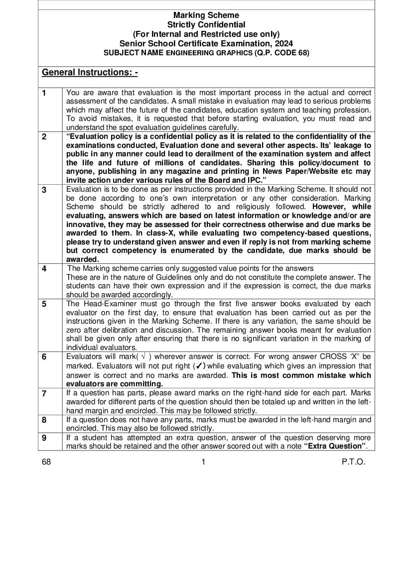
Strictly Confidential
(For Internal and Restricted use only)
Senior School Certificate Examination, 2024
SUBJECT NAME ENGINEERING GRAPHICS (Q.P. CODE 68)
General Instructions: -
1 You are aware that evaluation is the most important process in the actual and correct
assessment of the candidates. A small mistake in evaluation may lead to serious problems
which may affect the future of the candidates, education system and teaching profession.
To avoid mistakes, it is requested that before starting evaluation, you must read and
understand the spot evaluation guidelines carefully.
2 “Evaluation policy is a confidential policy as it is related to the confidentiality of the
examinations conducted, Evaluation done and several other aspects. Its’ leakage to
public in any manner could lead to derailment of the examination system and affect
the life and future of millions of candidates. Sharing this policy/document to
anyone, publishing in any magazine and printing in News Paper/Website etc may
invite action under various rules of the Board and IPC.”
3 Evaluation is to be done as per instructions provided in the Marking Scheme. It should not
be done according to one’s own interpretation or any other consideration. Marking
Scheme should be strictly adhered to and religiously followed. However, while
evaluating, answers which are based on latest information or knowledge and/or are
innovative, they may be assessed for their correctness otherwise and due marks be
awarded to them. In class-X, while evaluating two competency-based questions,
please try to understand given answer and even if reply is not from marking scheme
but correct competency is enumerated by the candidate, due marks should be
awarded.
4 The Marking scheme carries only suggested value points for the answers
These are in the nature of Guidelines only and do not constitute the complete answer. The
students can have their own expression and if the expression is correct, the due marks
should be awarded accordingly.
5 The Head-Examiner must go through the first five answer books evaluated by each
evaluator on the first day, to ensure that evaluation has been carried out as per the
instructions given in the Marking Scheme. If there is any variation, the same should be
zero after delibration and discussion. The remaining answer books meant for evaluation
shall be given only after ensuring that there is no significant variation in the marking of
individual evaluators.
6 Evaluators will mark( √ ) wherever answer is correct. For wrong answer CROSS ‘X” be
marked. Evaluators will not put right (✓)while evaluating which gives an impression that
answer is correct and no marks are awarded. This is most common mistake which
evaluators are committing.
7 If a question has parts, please award marks on the right-hand side for each part. Marks
awarded for different parts of the question should then be totaled up and written in the left-
hand margin and encircled. This may be followed strictly.
8 If a question does not have any parts, marks must be awarded in the left-hand margin and
encircled. This may also be followed strictly.
9 If a student has attempted an extra question, answer of the question deserving more
marks should be retained and the other answer scored out with a note “Extra Question”.
68 1 P.T.O.
Page 2
once.
11 A full scale of marks 70 has to be used. Please do not hesitate to award full marks if the
answer deserves it.
12 Every examiner has to necessarily do evaluation work for full working hours i.e., 8 hours
every day and evaluate 20 answer books per day in main subjects and 25 answer books
per day in other subjects (Details are given in Spot Guidelines).This is in view of the
reduced syllabus and number of questions in question paper.
13 Ensure that you do not make the following common types of errors committed by the
Examiner in the past:-
● Leaving answer or part thereof unassessed in an answer book.
● Giving more marks for an answer than assigned to it.
● Wrong totaling of marks awarded on an answer.
● Wrong transfer of marks from the inside pages of the answer book to the title page.
● Wrong question wise totaling on the title page.
● Wrong totaling of marks of the two columns on the title page.
● Wrong grand total.
● Marks in words and figures not tallying/not same.
● Wrong transfer of marks from the answer book to online award list.
● Answers marked as correct, but marks not awarded. (Ensure that the right tick mark
is correctly and clearly indicated. It should merely be a line. Same is with the X for
incorrect answer.)
● Half or a part of answer marked correct and the rest as wrong, but no marks awarded.
14 While evaluating the answer books if the answer is found to be totally incorrect, it should
be marked as cross (X) and awarded zero (0)Marks.
15 Any unassessed portion, non-carrying over of marks to the title page, or totaling error
detected by the candidate shall damage the prestige of all the personnel engaged in the
evaluation work as also of the Board. Hence, in order to uphold the prestige of all
concerned, it is again reiterated that the instructions be followed meticulously and
judiciously.
16 The Examiners should acquaint themselves with the guidelines given in the “Guidelines
for Spot Evaluation” before starting the actual evaluation.
17 Every Examiner shall also ensure that all the answers are evaluated, marks carried over to
the title page, correctly totaled and written in figures and words.
18 The candidates are entitled to obtain photocopy of the Answer Book on request on
payment of the prescribed processing fee. All Examiners/Additional Head Examiners/Head
Examiners are once again reminded that they must ensure that evaluation is carried out
strictly as per value points for each answer as given in the Marking Scheme.
68 2
Page 3
a) Marks are to be awarded in proportion to the work done.
b) Mistakes in dimensioning up to ± 1.0 mm may be ignored.
In dimensioning, arrow-heads of various types, as per SP: 46-2003 codes are acceptable.
c) However, where space is too small for an arrowhead, oblique stroke or dot may be
employed.
In question no. 21 and in sectioned view of question no. 23, if hidden edges / lines are
d) drawn, no marks should be deducted.
Other standard methods of drawing / proportions for isometric scale, nuts, heads of bolts,
e) screws etc. employed by examinees, may also be accepted.
The answers/solutions must be evaluated adhering to marking scheme and no marks
f) should be deducted without mistake.
68 3 P.T.O.
Page 4
MARKING SCHEME
ENGINEERING GRAPHICS
SECTION – A 20X1=20
1. (B) axonometric, oblique and perspective
2. (B) Isometric projection
3. (B) behind V.P. and above H.P.
4. (B) Actual scale
OR
(D) Isometric scale
5. (B) (ii) and (iv) only
6. (C) (ii) and (iii) only
7. (C) (iii)
8. (D) 1-(i), 2-(iii), 3-(iv), 4-(ii)
9. (C) (iv) only
10. (A) 1-(iv), 2-(iii), 3-(i), 4-(ii)
11. (D) 1-(ii), 2-(i), 3-(iv), 4-(iii)
12. (A) 8 mm
13. (A) internally
14. (D) one
15. (B) arcs, circle
68 4
Page 5
incomplete circle.
17. (C) Stud
18. (A) 12 mm
19. (D) plain stud
20. (B) 20 mm
SECTION – B
21. (A) CONSTRUCTION OF ISOMETRIC SCALE ` 5
(i) Drawing lines at an angle of 30 and 45 1
(ii) Marking of divisions of 10 mm, including division of first part of
1 mm on true length/scale 1:1 1
(iii) Projections from scale 1 : 1 to get points on isometric scale,
construction of isometric scale 2
(iv) Printing “True Length/Scale 1:1”, “Isometric Length/Isometric
Scale” and marking angles 300, 450 1
(B) ISOMETRIC PROJECTION OF PENTAGONAL PRISM 10
(i) Drawing helping figure of pentagon 2
(ii) Drawing upper isometric pentagon (2) and lower isometric
pentagon (1) keeping one base edge parallel to V.P. and away
from it. 3
(iii) Drawing vertical edges 3
(iv) Marking the axis (½) and direction of viewing (½) 1
(v) Dimensions 1
Note : For incorrect position, 1 mark should be deducted
68 5 P.T.O.
Page 6
(i) Marking of horizontal distances equal to half of pitch and one
horizontal centre line to create centre points of arcs 2
(ii) Drawing semi-circular arcs of radius 0.25P, showing crests and
roots of threads (minimum two) 3
(iii) Drawing hatching lines with conventional break 1
(iv) Standard dimensions 2
OR
(B) SQUARE HEADED BOLT 8
Front View
(i) Shank with threaded portion (length of bolt as 80mm) and
conventional end, drawn correctly 2
(ii) Head portion with chamfering, drawn correctly 2
Left Side View
(i) Left side view with chamfering circle and conventional
representation of threads, drawn correctly 2
Standard dimensions 2
Note :
1. For incorrect position or freehand sketch, 2 marks should be
deducted, in all.
2. The position of head of the square headed bolt can be drawn on
either side and must be projected accordingly in left side view.
68 6
Page 7
(i) Front view right half in section 13
- Drawing the right half of the body (2), sole recess (1) and
hatching lines (1) 4
- Drawing the right half of the bush (2) with hatching lines (1) 3
- Drawing left half of the body 2
- Drawing collar of the bush in left half 2
- Drawing the bolt hole in right half ( 1½ ) and axis of the bolt
hole in the left half ( ½ ) 2
(ii) Left side view 8
- Drawing the boundary of the body with one horizontal line for
sole at 18mm (2 ½) and hidden lines showing bolt hole and sole
recess (1 ½) 4
- Drawing the collar portion of bush on each side (2) with two
hidden lines (2) 4
DETAILS 6
Printing title (1), Scale used (1), Projection symbol (1), Six important
dimensions (3)
OR
68 7 P.T.O.
Page 8
(i) BODY
(a) Full sectional front view 8
- Drawing the outline of the body (2), drawing two bolt holes
indicating CRS (2), recess (1) 5 1
- Drawing inner circle of dia 44mm 1
- Drawing of oil hole 1
- Hatching lines 1
(b) Left side view 7
- Drawing the outline of the body with one horizontal line for
sole at 14mm 3
- Two horizontal hidden lines (1) and hidden lines showing bolt
hole and recess (2), hidden oil hole ( ½ ) 3½
- Cutting plane ½
(ii) BUSH
(a) Front view 3
- Two circles 2
- Hidden oil hole ( ½ ), cutting plane ( ½ ) 1
(b) Full sectional right side view 3
- Entire outline with two inner horizontal lines (2), oil hole ( ½ ) 2 ½
- Hatching lines ½
DETAILS 6
Printing titles (1), Scale used (1), Projection symbol (1), Six
important dimensions (3)
68 8
Page 9
m
21
70
(A)
60
50
TH
G
40
45°
N
LE
E
30
2 U
TR
70
0
60
30°
50
10
40 H
NGT
30 LE
0
2 0 IC
E TR
10
1 0 M
0 IS O
10
ISOMETRIC SCALE
21
(B)
50
25
HELPING FIGURE
25
30°
30°
ISOMETRIC PROJECTION
68 9 P.T.O.
Page 10
22 P
60 30 15
(A) 0.5P
25
P
=0.
R
d = 0.5P
KNUCKLE THREAD
OR
22
SQUARE HEADED BOLT
(B)
d 0.8d 1.5d+3 2d 2d+6 L
SOLUTION - 1 20 16 33 40 46 80
0.8d L 1.5d+3
2d+6
R=2d
R=d
Ø0.8d
Ød
SOLUTION - 2
FRONT VIEW LEFT SIDE VIEW
0.8 d L
1.
2d+6
5d
+3
60°
R=d
Ø0.8d
Ød
60°
30°
FRONT VIEW LEFT SIDE VIEW
68 10
Page 11
23 R6 20 8 8
(A)
30
R2
19
7
R
5
R6
50
R36
18
4
11
30 26 14 Ø18 10
210 68
FRONT VIEW, RIGHT HALF IN SECTION LEFT SIDE VIEW
SCALE - 1:1
ASSEMBLY OF OPEN BEARING
P.T.O.
Page 12
A
OR Ø8 FOR 4, THEN Ø4
Ø44
(i) BODY
23
(B)
Ø62
R4 14 4
10
14
3
7 CRS 90 7 A'
72 72 7 45 7
(ii) BUSH
12
FULL SECTIONAL FRONT VIEW LEFT SIDE VIEW
Ø4
B
44
Ø
Ø
36
SCALE 1:1
B'
FULL SECTIONAL RIGHT SIDE VIEW FRONT VIEW
DISASSEMBLY OF BUSH BEARING
Document Details
| Board / Org | CBSE |
| Exam | Class 12 |
| Type | Solution |
| Pages | 12 |
| Updated | 30 Apr 2026 |