CBSE Class 12 Physics Question Paper 2020 Set 55-2-1 Solutions
Finished viewing? Save it for later —
Download CBSE Class 12 Physics Question Paper 2020 Set 55-2-1 Solutions (PDF · 16 pages)About CBSE Class 12 Physics Question Paper 2020 Set 55-2-1 Solutions
CBSE Class 12 Physics Question Paper 2020 Set 55-2-1 Solutions is available here for free download. Published by CBSE for Class 12, this solution can be viewed online or downloaded as a PDF (16 pages). Candidates preparing for Class 12 can use CBSE Class 12 Physics Question Paper 2020 Set 55-2-1 Solutions to understand the exam pattern, the type of questions asked, and the overall difficulty level.
Frequently Asked Questions
How can I download CBSE Class 12 Physics Question Paper 2020 Set 55-2-1 Solutions?
Open this page and click the Download button to save CBSE Class 12 Physics Question Paper 2020 Set 55-2-1 Solutions as a PDF. It is completely free on AglaSem Docs.
Is CBSE Class 12 Physics Question Paper 2020 Set 55-2-1 Solutions free to download?
Yes. CBSE Class 12 Physics Question Paper 2020 Set 55-2-1 Solutions can be viewed online and downloaded as a PDF free of cost on AglaSem Docs.
How many pages does CBSE Class 12 Physics Question Paper 2020 Set 55-2-1 Solutions have?
CBSE Class 12 Physics Question Paper 2020 Set 55-2-1 Solutions contains 16 pages, which you can read online or download together as a single PDF.
Where can I find more Class 12 study material?
You can find more Class 12 question papers, sample papers, syllabus, and answer keys on AglaSem Docs.
CBSE Class 12 Physics Question Paper 2020 Set 55-2-1 Solutions – Text
Read the full text of this solution below — useful to quickly search, copy and reference the content online without downloading the PDF.
📄 View text version (16 pages)
Page 1
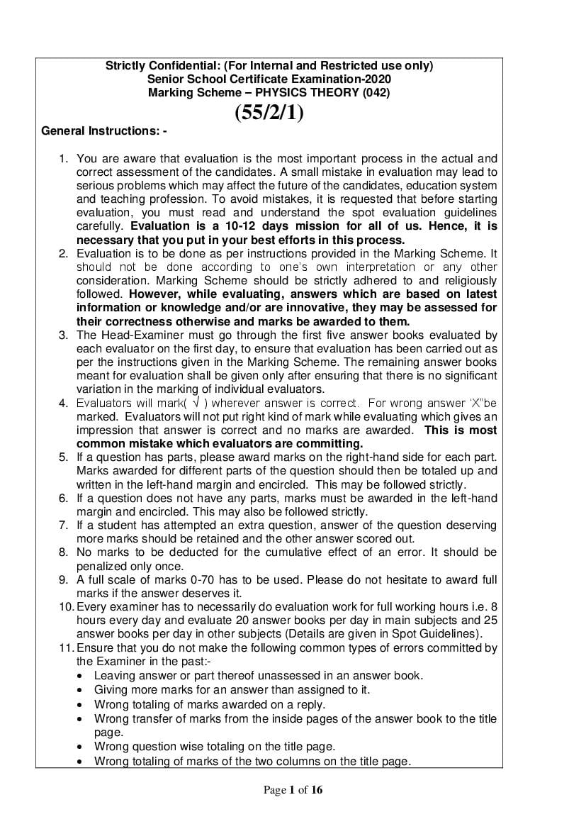
Senior School Certificate Examination-2020
Marking Scheme – PHYSICS THEORY (042)
(55/2/1)
General Instructions: -
1. You are aware that evaluation is the most important process in the actual and
correct assessment of the candidates. A small mistake in evaluation may lead to
serious problems which may affect the future of the candidates, education system
and teaching profession. To avoid mistakes, it is requested that before starting
evaluation, you must read and understand the spot evaluation guidelines
carefully. Evaluation is a 10-12 days mission for all of us. Hence, it is
necessary that you put in your best efforts in this process.
2. Evaluation is to be done as per instructions provided in the Marking Scheme. It
should not be done according to one’s own interpretation or any other
consideration. Marking Scheme should be strictly adhered to and religiously
followed. However, while evaluating, answers which are based on latest
information or knowledge and/or are innovative, they may be assessed for
their correctness otherwise and marks be awarded to them.
3. The Head-Examiner must go through the first five answer books evaluated by
each evaluator on the first day, to ensure that evaluation has been carried out as
per the instructions given in the Marking Scheme. The remaining answer books
meant for evaluation shall be given only after ensuring that there is no significant
variation in the marking of individual evaluators.
4. Evaluators will mark( √ ) wherever answer is correct. For wrong answer ‘X”be
marked. Evaluators will not put right kind of mark while evaluating which gives an
impression that answer is correct and no marks are awarded. This is most
common mistake which evaluators are committing.
5. If a question has parts, please award marks on the right-hand side for each part.
Marks awarded for different parts of the question should then be totaled up and
written in the left-hand margin and encircled. This may be followed strictly.
6. If a question does not have any parts, marks must be awarded in the left-hand
margin and encircled. This may also be followed strictly.
7. If a student has attempted an extra question, answer of the question deserving
more marks should be retained and the other answer scored out.
8. No marks to be deducted for the cumulative effect of an error. It should be
penalized only once.
9. A full scale of marks 0-70 has to be used. Please do not hesitate to award full
marks if the answer deserves it.
10. Every examiner has to necessarily do evaluation work for full working hours i.e. 8
hours every day and evaluate 20 answer books per day in main subjects and 25
answer books per day in other subjects (Details are given in Spot Guidelines).
11. Ensure that you do not make the following common types of errors committed by
the Examiner in the past:-
Leaving answer or part thereof unassessed in an answer book.
Giving more marks for an answer than assigned to it.
Wrong totaling of marks awarded on a reply.
Wrong transfer of marks from the inside pages of the answer book to the title
page.
Wrong question wise totaling on the title page.
Wrong totaling of marks of the two columns on the title page.
Page 1 of 16
Page 2
Marks in words and figures not tallying.
Wrong transfer of marks from the answer book to online award list.
Answers marked as correct, but marks not awarded. (Ensure that the right tick
mark is correctly and clearly indicated. It should merely be a line. Same is with
the X for incorrect answer.)
Half or a part of answer marked correct and the rest as wrong, but no marks
awarded.
12. While evaluating the answer books if the answer is found to be totally incorrect, it
should be marked as cross (X) and awarded zero (0)Marks.
13. Any unassessed portion, non-carrying over of marks to the title page, or totaling
error detected by the candidate shall damage the prestige of all the personnel
engaged in the evaluation work as also of the Board. Hence, in order to uphold
the prestige of all concerned, it is again reiterated that the instructions be followed
meticulously and judiciously.
14. The Examiners should acquaint themselves with the guidelines given in the
Guidelines for spot Evaluation before starting the actual evaluation.
15. Every Examiner shall also ensure that all the answers are evaluated, marks
carried over to the title page, correctly totaled and written in figures and words.
16. The Board permits candidates to obtain photocopy of the Answer Book on request
in an RTI application and also separately as a part of the re-evaluation process
on payment of the processing charges.
Page 2 of 16
Page 3
Code : 55/2/1
Q.No. Value Points/Expected Answer Marks Total
Marks
SECTION A
1 (D) R = 0 1 1
2 (A) Resistivity 1 1
3 (A) move in a straight line. 1 1
4 (B) ferromagnetic material becomes paramagnetic 1 1
5 (A) electric field is changing 1 1
6 (A) X – rays 1 1
7 (C) zero as diffusion and drift current are equal and opposite. 1 1
8 (B) just below the conduction band 1 1
9 (A) binding energy per nucleon increases 1 1
10 (A) neutron converts into a proton emitting antineutrino. 1 1
11 (∅2 − ∅1 )ε0 / (∅1 − ∅2 )ε0 1 1
12 Third 1 1
OR
2λ
[Alternatively, broader]
a
13 Small/ shorter 1 1
14 Perpendicular 1 1
15 Blue 1 1
16 1 1 1
Xc = OR Z=R
2πνC
17 Zero 1 1
18
1 1
Alternatively
19 6.03 × 10⁻⁷ m 1 1
[Award full 1 mark even if a student writes 6 × 10⁻⁷ m]
20 For a given photosensitive material, there exists a certain 1 1
minimum cut-off frequency of the incident radiation, called the
threshold frequency, below which no emission of photo electrons
takes place, no matter how intense the incident light is.
SECTION B
21
Definition of mobility or formula 1
Derivation of relationship 1
Mobility is defined as the magnitude of drift velocity per unit
electric field.
⃗⃗⃗⃗d |
|V 1
μ=
E
[Even if a student writes only the mathematical relation award ½
mark]
eτE
Given Vd = ½ 2
m
Vd eτ
Hence, μ = =
E m ½
OR
Page 3 of 16
Page 4
Relation between current density and drift velocity 1
The average speed with which electrons move when an electric
field or potential difference is applied is called drift velocity.
−eE⃗τ 1
⃗⃗⃗⃗
Vd =
m
[Award 1/2mark if student writes the formulae]
The amount of charge crossing the area A in time Δ𝑡
⃗⃗⃗⃗d | Δt
IΔt = ne A |V
Hence current density ½
I
j = = ne Vd
A
½ 2
22
Diagram ½
Formula ½
Calculation of value of shunt 1
½
Ig = 1 A
Resistance of ammeter, RA = 0.8 Ω
Ig 𝑅𝐴 = (I − Ig ) S 1
⇒ 1 × 0.8 = (5 − 1) S
⇒ S = 0.2 Ω ½ 2
23
(a) Sharpness of resonance 1
(b) Value of power factor 1
(a)
Sharpness of resonance is the sharpness of the peak of the
resonance curve / a graph between 𝐼𝑚 and 𝜔. The sharper or
narrower the curve the narrower is the resonance or the resonance
lasts over a very small range of frequencies /
Q factor or quality factor is the measure of sharpness of curve. 1
(b)
Z=R
Hence Power factor
R
cos ∅ =
Z
Page 4 of 16
Page 5
Even if a student just writes power factor is 1, award full 1 mark 1 2
OR
Deduction of expression for current 1
(i) Graph V vs ωt ½
(ii) Graph I vs ωt ½
dq 𝑑 ½
I= = C V sin ωt = ωCV0 cos ωt
dt 𝑑𝑡 0
= I0 cos ωt
π
= I0 sin (ωt + ) ½
2
V0
where I0 = 1
( ⁄ωC)
(i)
1
2
[Student can draw the two graphs separately also provided the
graphs are co-related.]
24
Identification of waves (a) & (b) ½+½
Uses ½+½
(a) minimum wavelength: 𝛾 rays ½
(b) minimum frequency: Microwaves ½
𝛾 rays are used to treat cancer ½
Microwaves are used for communication ½ 2
[or any other correct use]
25
Values of f and u with sign conventions ½
Nature of image ½
Position of image 1
−𝑅 ½
The focal length 𝑓 = = −30 𝑐𝑚 𝑢 = −20 𝑐𝑚
2
1 1 1
+ = ½
𝑉 𝑢 𝑓
1 1 1 1 1 1
∴ − =− ⇒ = − +
𝑉 20 30 𝑉 30 20 ½
∴ 𝑉 = +60 𝑐𝑚
Nature of image: virtual, erect and magnified ½ 2
Page 5 of 16
Page 6
Identification of b and θ ½+½
Values of b ½+½
(a) b represents impact parameter ½
𝜃 represents scattering angle ½
(b) (i) for 𝜃 = 00 impact parameter is large or infinite ½
(ii) for 𝜃 = 1800 impact parameter is zero. ½ 2
27 V-I characteristics 1
Explanation for voltage independence of reverse current 1
1
Since reverse current is due to flow of minority charge carriers
across the junction, it is limited due to the concentration of minority
carriers on either side of the junction. It is therefore independent of 1 2
the voltage applied.
SECTION C
28
(a) Magnitude & direction of net dipole moment 1½
(b) Magnitude & direction of net torque 1½
(a)
½
1
𝑃 = (𝑝12 + 𝑝22 + 2 𝑝1 𝑝2 cos 1200 ) ⁄2
1
= (2𝑝2 − 𝑝2 ) ⁄2 ½
=p
0
Making 60 angle with ⃗⃗⃗ 𝑝1 and α = 300 (angle with X axis) ½
[p1 = p2 = p]
[Do not deduct ½ mark if diagram is not drawn but dipole moment
and its direction are correctly worked out.
Page 6 of 16
Page 7
moment is not worked out then award 1 mark out of 1.5] ½
(b)
⃗τ = ⃗P × ⃗E ½
τ = PE sin 300
1 ½
= pE 3
2
Direction of 𝜏 is into the plane of the paper or along -z direction.
OR
(a) Equivalent capacitance 1
(b) Maximum charge supplied 1 1
(c) Total energy stored 1 ½
(a) C = C4 = 4μF (as C1, C2, C4, C5 are short circuited) ½
(b) Q = CV = 4 × 7 μC ½
= 28 μC
1 ½
(c) 𝒰 = CV 2
2 3
1
= × 4 × 10−6 × 7 × 7 = 98 × 10−6 J
2
29
(a) Derivation of balance condition 2
(b) Circuit diagram 1
(a)
½
In a balanced Wheatstone bridge 𝐼𝑔 = 0
∴ I1 = I3 and I2 = I4
Applying loop rule in ADBA
−I1 R1 + 0 + I2 R 2 = 0
I1 R2 ½
⇒ = (i)
I2 R1
And in loop CBDC
I2 R 4 + 0 − I1 R 3 = 0
I1 R4 ½
⇒ = (ii)
I2 R3
From (i) and (ii)
R2 R4
= ½
R1 R3
Condition for balanced Wheatstone bridge
Page 7 of 16
Page 8
3
1
30
(a) Capacitance of the capacitor 1
(b) Value of inductance 1
(c) Graph 1
(a) From graph Xc = 6 Ω at υ = 100 Hz
1 1 ½
Xc = =
ωC 2πυC
1 1
C= =
2πυXc 2π × 600
1
C= = 0.265mF = 0.265 × 10⁻³ 𝑓 ½
1200 π
Even if a student evaluates part(a)correctly using
[ ]
any other point on the graph, award full 1 mark.
(b)
XC = XL = ωL = 6 at 100 Hz ½
6
L=
2πυ
6
= = 0.955 × 10⁻² H ½
2π × 100
(c)
1 3
31
Differences in construction 1 mark
Determination of position of object 2 marks
Aperture of telescope objective lens is large whereas aperture of
½
microscope objective is small
fo>fe in telescope
½
fo<fe in microscope
[Alternatively, focal length of telescope objective is large whereas
focal length of microscope objective is very small]
[Award full 1 mark even if a student writes only one difference]
Page 8 of 16
Page 9
D 25
me = 1 + = 1 + =6
fe 5
30
∴ mo = = −5 ½
6
v
mo = = −5
u
v = −5u
1 1 1 ½
= −
f v u
1 1 1
= + ; u = −u0
1.25 5uo u0
6 ½ 3
u0 = × 1.25 = 1.5cm
5
𝑣 𝑓
[Alternatively, 𝑚𝑜 = = 𝑜
𝑢 𝑓𝑜 +𝑢𝑜
1.25
−5 =
1.25 + uo
−7.5 = 5uo
uo = −1.5cm ( for last ½ mark) ]
32
Deduction of expression for threshold wavelength 2 marks
Deduction of expression for work function 1 mark
hc 1 1
K max = − ϕo = hc ( − ) ½
λ1 λ1 λo
when λ = λ2
1 1
2K max = hc ( − ) ½
λ2 λo
1 1
K max 1 (λ1 − λ0 )
= = ½
2K max 2 ( 1 − 1 )
λ2 λ0
λ1 λ2
λo = = Threshold wavelength ½
2λ2 − λ1
hc hc(2λ2 − λ1 )
ϕo = = 1 3
λo (λ1 λ2 )
33
a) Differentiation between Half life and Average life
½+½
b) Deduction of fraction of amount of the substance 2
Half life is the time it takes for a radioactive sample, that has ½
N
initially No radio nuclei, to reduce to 0
2
ln 2 0.693
T1⁄ = =
2 λ 𝜆
Mean life is obtained by adding the lives of all the nuclei over time
0 to infinity and dividing it by total number No of nuclei at t=0 ½
τ = 1/λ
Page 9 of 16
Page 10
marks for the definitions]
N = No e−λt
½
At t = τ = 1/λ
1
N = N0 e−λ×λ ½
N 1
= 1
No e 3
34
Function of solar cell 1 mark
Working of solar cell 1 ½ mark
IV characteristics ½ mark
Solar cell is a device which converts solar energy into electrical
energy. 1
[Alternatively, when solar radiation falls on a solar cell, it
generates emf.]
Working
When solar radiation falls on a solar cell three important
phenomena occur
1) Generation: e-h pair generation near the depletion region ½
2) Separation: e-h will separate due to the electric field in ½
depletion region
3) Collection- electrons are collected by front contact on n side ½
and holes are collected by back contact on p side.
Thus, a potential difference will be created.
½ 3
SECTION D
35
(a) Expression for electric field outside a charged shell 2
Graph of E vs r 1
b) Location of point where field is zero 2
(a)
½
Page 10 of 16
Page 11
ϕ=
ϵ0
2
σ(4πR2 ) ½
E × 4πr =
ϵ0
1 q ½
E=
4πϵo r 2
[∴ q = σ(4πR2 ]
which is electric field due to a point charge q at a distance r from it
1
For r<R, E=0 because q=0 inside the shell
(b)
½
E1=E2
1 1 × 10⁻⁶ 1 4 × 10⁻⁶ ½
=
4𝜋𝜖𝑜 𝑥2 4𝜋𝜖𝑜 (0.3 − 𝑥)2
½
(0.3 − 𝑥) = 4𝑥 2
2
5
0.3 − 𝑥 = 2𝑥
½
𝑥 = 0.1𝑚 = 10 𝑐𝑚 (𝑡𝑜 𝑡ℎ𝑒 𝑟𝑖𝑔ℎ𝑡 𝑜𝑓 𝑞1 )
OR
a) Work done in assembling the system 2
b) (i) Evaluation of electric field 1½
(ii) Electric flux through the cube 1½
(a)
The work done in bringing charge q1 from infinity to r1 is
W1 = q1 V1 ½
The work done in bringing charge q2 from infinity to r2 is
W2 = q2 V2 ½
Work done in moving q2 against the field due to q1
1 q1 q 2 ½
W3 =
4πϵo r
Hence total work done is W = W1 + W2 + W3
Page 11 of 16
Page 12
W = q1 V1 + q2 V2 +
4πϵo r
[V1 and V2 are potentials at the two points in the electric field]
(b)
(i)
−dV 𝑑 1
E= = − (10𝑥 + 5)
dx 𝑑𝑥
⃗
∴ E = −10î N/C ½
(ii) Electric flux through the cube, 𝜙 =sum of electric flux through
6 faces
Electric flux through faces perpendicular Y and Z axis = 0 ½
∵ E is along x axis
Electric flux through faces perpendicular to x axis
= 𝜙1 + 𝜙2 ½
= 10 × (0.2)2 − 10 × (0.2)2
=0 ½ 5
36
(a) Magnetic field at a point on the axis of the current loop 3
(b)Magnitude and direction of the magnetic force 2
(a)
½
0 Idl
dB ½
4 ( x 2 R 2 )
dB has two components dBx and dB , perpendicular components
from diametrically opposite elements dl cancel out, thus only dB x
components remain effective
𝑑Bx = dB cosθ ½
R
and cos θ = 1
(x 2 + R2 )2
∴ B = ∫ dBx
2πR μ0 IdlR
=∫ ½
3
0 4π(x 2 + R2 )2
Page 12 of 16
Page 13
= 3 1
2(x 2 + R2 )2
along the axis of the loop
(b)
(i)
½
⃗⃗⃗⃗
⃗F = I[l × B] ½
F = IlB sin θ
= 5 × 2 × 0.6 × 10−4 × 0.5 = 3 × 10⁻⁴ N ½
(ii) Towards east
½ 5
OR
(a) Derivation of torque 2
Reason of radial magnetic field 1
(b) Kinetic Energy of the particle 2
(a)
½
Arms AD and BC experience no net force whereas arm AB and
CD experience forces which constitute torque
½
F1 = F2 = IbB
Therefore magnitude of torque
Page 13 of 16
Page 14
F1 F2 sin
2 2
I (ab) sin
where ab A(area of the loop )
IAB sin ½
for N number of turns
NIAB sin
M B
Where magnetic moment M=NIA
Galvanometer has Radial magnetic field to increase the field
1
strength and to make torque independent of orientation 𝜃/ it
maximise the torque
(b)
1 𝑞2 𝐵2 𝑅2
½
The kinetic energy 𝐾𝐸 =
2 𝑚
2
1 (1.6 ×10⁻¹⁹ ) ×(0.4)2 × (0.4)2
= × 𝐽 ½
2 1.6 ×10⁻²⁷
2
(1.6 ×10⁻¹⁹ ) ×(0.4)2 × (0.4)2
= 𝑒𝑉 ½
2 ×1.6 ×10−27 ×1.6 ×10−19
= 1.28 𝑀𝑒𝑉 ½ 5
37
(a) Derivation of the lens maker’s formula 2½
(b) Ray diagram 1
(c) Focal length of the mirror 1½
(a)
½
½
Page 14 of 16
Page 15
μ2 μ μ2 −μ1
− 1= ---------------------------1 ½
v1 u R1
For second refracting surface ADC
μ1 μ μ −μ
− 2 = 1 2-------------------------------2
v v1 R2
Adding equations 1 and 2, we get
μ1 μ1 1 1
− = (μ2 − μ1 ) [ − ] ½
v u R1 R 2
1 1 μ2 1 1
⇒ − = ( − 1) [ − ]
v u μ1 R1 R 2
1 1 1
∵ − =
v u f
1 μ2 1 1 ½
∴ = ( − 1) [ − ]
f μ1 R1 R 2
also
μ2
=μ
μ1
1 1 1
∴ = (μ − 1) [ − ]
f R1 R 2
(b)
1
f1 10 cm
u 12 cm
Aplying lens formula
1 1 1
½
f v u
1 1 1
10 v 12
v 60 cm ½
radius of curvature of the mirror
R 60 cm 10 cm 50 cm
R 5
hence focal length of the morror f m 25 cm ½
2
OR
(a) Definition of wavefront ½
Propagation of wavefront ½
Verification of law of refraction 2
(b) (i) Determination of width of the slit 1
(ii) Calculation of distance of secondary maxima 1
Page 15 of 16
Page 16
Wavefront is a surface of constant phase. ½
Alternatively, It is the locus of all those points which are in the
same phase of disturbance.
The wave propagates in a direction perpendicular to the ½
wavefront through secondary wavelets originating from
different points on it.
½
Consider a plane wave AB incident at an angle I with speed v on
the surface MN in time τ
Therefore
BC=v τ ½
Using Huygen’s principle, a sphere of radius v τ which has
tangent plane CE is reflected at an angle r
AE BC v ½
∵ ∆𝐸𝐴𝐶 and ∆𝐵𝐴𝐶are congruent
½
∵ ∠𝑖 = ∠𝑟
(b)
(i) ½
λD
x=
d
λD 500 × 10−9 × 1 ½
⇒d= = = 2 × 10−4 m
x 2.5 × 10−3
(ii) For the first Secondary maxima
3λD
x= ½
2d
3×500×10−9 ×1
= =3.75mm ½ 5
2×2×10−4
[Even if a student finds location of first secondary maxima by
1
(2.5)+ ( × 2.5) =3.75mm, award full 1 mark for b(ii)]
2
Page 16 of 16
Document Details
| Board / Org | CBSE |
| Exam | Class 12 |
| Type | Solution |
| Pages | 16 |
| Updated | 22 Jul 2026 |