CBSE Class 12 Sample Paper 2023 Engineering Graphics
Finished viewing? Save it for later —
Download CBSE Class 12 Sample Paper 2023 Engineering Graphics (PDF · 11 pages)About CBSE Class 12 Sample Paper 2023 Engineering Graphics
CBSE Class 12 Sample Paper 2023 Engineering Graphics is available here for free download. Published by CBSE for Class 12, this sample paper can be viewed online or downloaded as a PDF (11 pages). Candidates preparing for Class 12 can use CBSE Class 12 Sample Paper 2023 Engineering Graphics to understand the exam pattern, the type of questions asked, and the overall difficulty level.
Frequently Asked Questions
How can I download CBSE Class 12 Sample Paper 2023 Engineering Graphics?
Open this page and click the Download button to save CBSE Class 12 Sample Paper 2023 Engineering Graphics as a PDF. It is completely free on AglaSem Docs.
Is CBSE Class 12 Sample Paper 2023 Engineering Graphics free to download?
Yes. CBSE Class 12 Sample Paper 2023 Engineering Graphics can be viewed online and downloaded as a PDF free of cost on AglaSem Docs.
How many pages does CBSE Class 12 Sample Paper 2023 Engineering Graphics have?
CBSE Class 12 Sample Paper 2023 Engineering Graphics contains 11 pages, which you can read online or download together as a single PDF.
Where can I find more Class 12 study material?
You can find more Class 12 question papers, sample papers, syllabus, and answer keys on AglaSem Docs.
CBSE Class 12 Sample Paper 2023 Engineering Graphics – Text
Read the full text of this sample paper below — useful to quickly search, copy and reference the content online without downloading the PDF.
📄 View text version (11 pages)
Page 1
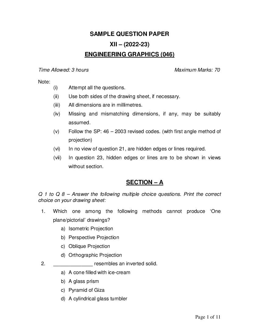
XII – (2022-23)
ENGINEERING GRAPHICS (046)
Time Allowed: 3 hours Maximum Marks: 70
Note:
(i) Attempt all the questions.
(ii) Use both sides of the drawing sheet, if necessary.
(iii) All dimensions are in millimetres.
(iv) Missing and mismatching dimensions, if any, may be suitably
assumed.
(v) Follow the SP: 46 – 2003 revised codes. (with first angle method of
projection)
(vi) In no view of question 21, are hidden edges or lines required.
(vii) In question 23, hidden edges or lines are to be shown in views
without section.
SECTION – A
Q 1 to Q 8 – Answer the following multiple choice questions. Print the correct
choice on your drawing sheet:
1. Which one among the following methods cannot produce ‘One
plane/pictorial’ drawings?
a) Isometric Projection
b) Perspective Projection
c) Oblique Projection
d) Orthographic Projection
2. ______________ resembles an inverted solid.
a) A cone filled with ice-cream
b) A glass prism
c) Pyramid of Giza
d) A cylindrical glass tumbler
Page 1 of 11
Page 2
whose axis is perpendicular to H.P and one of its base edges is parallel to
V.P.?
4. A gasket in Flange Pipe Joint is provided to
a) align the two flanges.
b) check leakage of fluid in pipes.
c) support the nuts and bolts.
d) fill the gap between the flanges.
5. The joint used for tightening of electric overhead wires is
a) Spigot and Socket Joint
b) Turn Buckle / Tie Rod Joint
c) Gib and Cotter Joint
d) Knuckle Joint
Page 2 of 11
Page 3
a) Centre to centre distance
b) Edge to edge distance
c) Corner to corner distance
d) Top to bottom distance
7. P.C.D. in flange pipe joint means
a) Pitch corner diameter
b) Pitch counter distance
c) Pitch centre distance
d) Pitch circle diameter
8. Usually taper in cotter is given as
a) 1 in 10
b) 1 in 20
c) 1 in 30
d) 1 in 40
Q 9 to Q 14 – Select the correct option corresponding to the orientation of the
given Isometric Projection:
9.
a) The hexagonal ends are parallel to VP
b) The pentagonal ends are parallel to VP
c) The hexagonal ends are perpendicular to VP
d) The pentagonal ends are perpendicular to VP
Page 3 of 11
Page 4
a) Axis of cone is perpendicular to HP, axis of prism is parallel to VP
b) Axis of cone is perpendicular to VP, axis of prism is parallel to HP
c) Axis of cone is perpendicular to HP, axis of prism is perpendicular
to VP
d) Axis of cone is parallel to VP, axis of prism is perpendicular to HP
Page 4 of 11
Page 5
a) A pentagonal prism is resting on top of pentagonal disc. Axis of
prism is parallel to VP and that of disc is perpendicular to VP.
b) A hexagonal prism is resting on top of hexagonal disc. Axis of prism
is perpendicular to HP and that of disc is parallel to VP.
c) A hexagonal prism is resting on top of pentagonal disc. Axis of
prism is parallel to VP and that of disc is perpendicular to HP.
d) A pentagonal prism is resting on top of hexagonal disc. Axis of
prism is parallel to VP and that of disc is perpendicular to HP.
Page 5 of 11
Page 6
a) Two vertical prisms where one of the base edges of the prism at
the rear is perpendicular to HP
b) Two vertical pyramids with one base edge of the pyramid is parallel
to VP and nearer to it
c) Two vertical solids with one base edge of the pyramid away from
observer and parallel to VP
d) Two horizontal solids with one base edge of the prism parallel to
VP and nearer to it
Page 6 of 11
Page 7
a) The length of common axis is true 65mm
b) The length of common axis is iso 65mm
c) The length of common axis is more than iso 65mm
d) The length of common axis is less than iso 65mm
14.
a) A horizontal solid placed on a vertical solid
b) A horizontal solid placed on a horizontal solid
c) A vertical solid placed on a horizontal solid
d) A vertical solid placed on a vertical solid
Page 7 of 11
Page 8
labelled reason (R). Select the correct answer to the following question from
the codes (a), (b), (c) and (d) as given below:
a) Both A and R are true and R is the correct explanation of A.
b) Both A and R are true and R is not the correct explanation of A.
c) A is true but R is false.
d) A is false and R is also false.
15. A: ‘Four centre method’ is used while drawing isometric view of a
hemisphere.
R: The iso projection of its circular face is a sphere.
Q16 to Q 20 – Answer Read the following para and answer the following
questions.
Two friends who are the students of class XII Engg. Graphics had to fix
the problems in their bike during the summer vacation. While purchasing the
spare parts at a machinery shop, they observed a machine part similar to bolt.
They sent the following image of that machine part to their Engg. Graphics
teacher. Then the teacher explained everything about that part, which is called as
stud.
16. Which category does the stud belong to?
a) Permanent fastner
b) Permanent bearing
c) Temporary fastener
d) Temporary bearing
Page 8 of 11
Page 9
a) Headless bolt
b) Headless key
c) Square headed bolt
d) Hexagonal headed bolt
18. Name the shape of the central portion of the above figure
a) Collar
b) Web
c) Cover
d) Rod
19. What is the outer diameter of the central portion of the above figure, when
‘d’ is the diameter of stud?
a) 0.8 d
b) d
c) 1.1 d
d) 1.5 d
20. What is the length of the metal end of a stud with 20mm diameter?
a) 46mm
b) 43mm
c) 20mm
d) 16mm
SECTION – B
21. (a) Construct an isometric scale. 5
(b) Draw the isometric projection of a pentagonal prism (base edge 25 mm,
axial length 55mm) resting on its face with its axis parallel to H.P. and
V.P. both. Indicate the direction of viewing. Give all the dimensions. 10
22. Draw to scale 1:1, the standard profile of the Metric thread profile
(Internal) with the pitch = 50mm. Give standard dimensions. 8
Page 9 of 11
Page 10
Draw to scale 1:1, the front view and top view of a square headed nut
across flat, the diameter is given as 25 mm. The axis of the nut is vertical.
Give the standard dimensions. 8
23. Figure 1 shows the details parts of an Open Bearing. Assemble all the parts
correctly and then draw to scale 1:1; it’s following views:
(a) Front View, right half in section 13
(b) Top View 8
Print the title and scale used. Draw projection symbol. Give 6 important
dimensions. 6
Figure 1
OR
Figure 2 shows the assembly of a ‘Gib and Cotter Joint’. Disassemble the parts
correctly and then draw to scale 1:1 its following views of the following
components. Keeping the same position with respect to H.P and V.P. as given:
Page 10 of 11
Page 11
(i) Front View, Upper half in section. 9
(ii) Top View. 6
(b) GIB
(i) Front View. 4
(ii) Side View. 2
(c) Print the titles of both and scale used. Draw the projection symbol.
Give 6 important dimensions. 6
Figure 2
Page 11 of 11
Document Details
| Board / Org | CBSE |
| Exam | Class 12 |
| Type | Sample Paper |
| Pages | 11 |
| Updated | 22 Jul 2026 |