CBSE Class 12 Question Paper 2022 Solution Physics
Finished viewing? Save it for later —
Download CBSE Class 12 Question Paper 2022 Solution Physics (PDF · 35 pages)About CBSE Class 12 Question Paper 2022 Solution Physics
CBSE Class 12 Question Paper 2022 Solution Physics is available here for free download. Published by CBSE for Class 12, this solution can be viewed online or downloaded as a PDF (35 pages). Candidates preparing for Class 12 can use CBSE Class 12 Question Paper 2022 Solution Physics to understand the exam pattern, the type of questions asked, and the overall difficulty level.
Frequently Asked Questions
How can I download CBSE Class 12 Question Paper 2022 Solution Physics?
Open this page and click the Download button to save CBSE Class 12 Question Paper 2022 Solution Physics as a PDF. It is completely free on AglaSem Docs.
Is CBSE Class 12 Question Paper 2022 Solution Physics free to download?
Yes. CBSE Class 12 Question Paper 2022 Solution Physics can be viewed online and downloaded as a PDF free of cost on AglaSem Docs.
How many pages does CBSE Class 12 Question Paper 2022 Solution Physics have?
CBSE Class 12 Question Paper 2022 Solution Physics contains 35 pages, which you can read online or download together as a single PDF.
Where can I find more Class 12 study material?
You can find more Class 12 question papers, sample papers, syllabus, and answer keys on AglaSem Docs.
CBSE Class 12 Question Paper 2022 Solution Physics – Text
Read the full text of this solution below — useful to quickly search, copy and reference the content online without downloading the PDF.
📄 View text version (35 pages)
Page 1
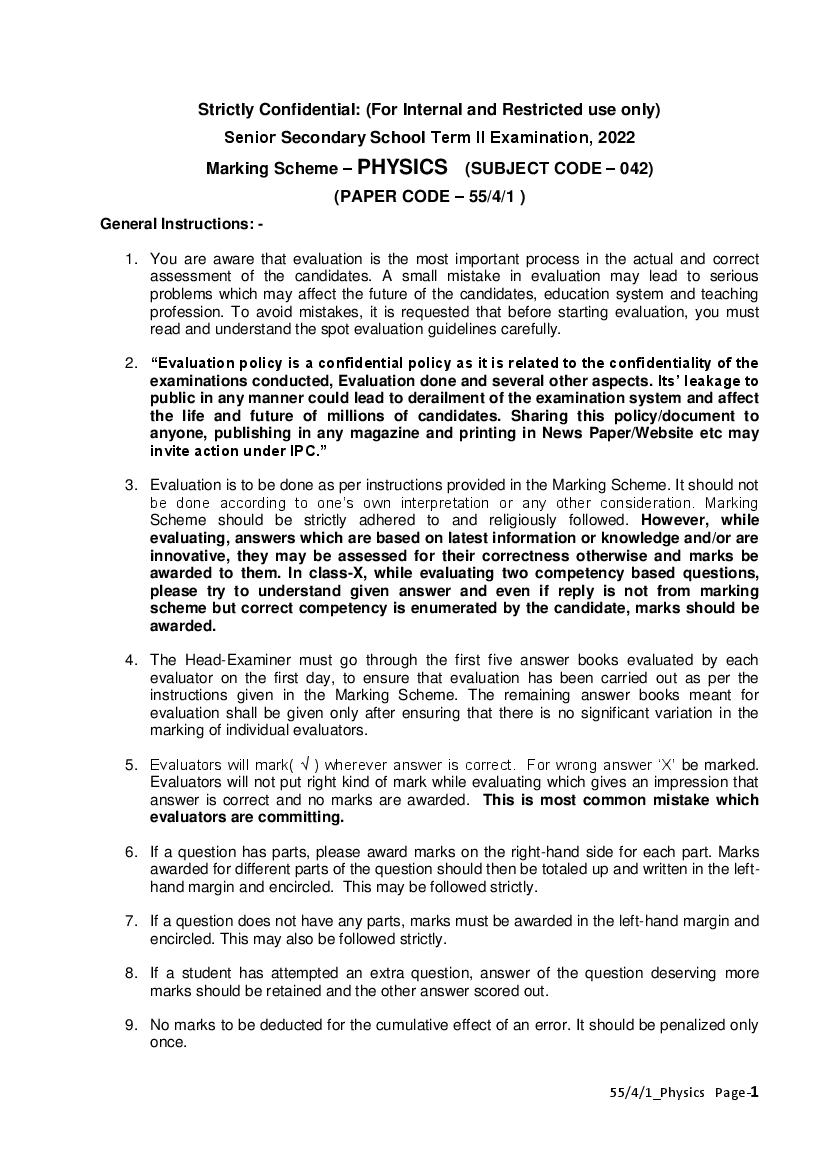
Senior Secondary School Term II Examination, 2022
Marking Scheme – PHYSICS (SUBJECT CODE – 042)
(PAPER CODE – 55/4/1 )
General Instructions: -
1. You are aware that evaluation is the most important process in the actual and correct
assessment of the candidates. A small mistake in evaluation may lead to serious
problems which may affect the future of the candidates, education system and teaching
profession. To avoid mistakes, it is requested that before starting evaluation, you must
read and understand the spot evaluation guidelines carefully.
2. “Evaluation policy is a confidential policy as it is related to the confidentiality of the
examinations conducted, Evaluation done and several other aspects. Its’ leakage to
public in any manner could lead to derailment of the examination system and affect
the life and future of millions of candidates. Sharing this policy/document to
anyone, publishing in any magazine and printing in News Paper/Website etc may
invite action under IPC.”
3. Evaluation is to be done as per instructions provided in the Marking Scheme. It should not
be done according to one’s own interpretation or any other consideration. Marking
Scheme should be strictly adhered to and religiously followed. However, while
evaluating, answers which are based on latest information or knowledge and/or are
innovative, they may be assessed for their correctness otherwise and marks be
awarded to them. In class-X, while evaluating two competency based questions,
please try to understand given answer and even if reply is not from marking
scheme but correct competency is enumerated by the candidate, marks should be
awarded.
4. The Head-Examiner must go through the first five answer books evaluated by each
evaluator on the first day, to ensure that evaluation has been carried out as per the
instructions given in the Marking Scheme. The remaining answer books meant for
evaluation shall be given only after ensuring that there is no significant variation in the
marking of individual evaluators.
5. Evaluators will mark( √ ) wherever answer is correct. For wrong answer ‘X’ be marked.
Evaluators will not put right kind of mark while evaluating which gives an impression that
answer is correct and no marks are awarded. This is most common mistake which
evaluators are committing.
6. If a question has parts, please award marks on the right-hand side for each part. Marks
awarded for different parts of the question should then be totaled up and written in the left-
hand margin and encircled. This may be followed strictly.
7. If a question does not have any parts, marks must be awarded in the left-hand margin and
encircled. This may also be followed strictly.
8. If a student has attempted an extra question, answer of the question deserving more
marks should be retained and the other answer scored out.
9. No marks to be deducted for the cumulative effect of an error. It should be penalized only
once.
55/4/1_Physics Page-1
Page 2
answer deserves it.
11. Every examiner has to necessarily do evaluation work for full working hours i.e. 8 hours
every day and evaluate 30 answer books per day in main subjects and 35 answer books
per day in other subjects (Details are given in Spot Guidelines).This is in view of the
reduced syllabus and number of questions in question paper.
12. Ensure that you do not make the following common types of errors committed by the
Examiner in the past:-
Leaving answer or part thereof unassessed in an answer book.
Giving more marks for an answer than assigned to it.
Wrong totaling of marks awarded on a reply.
Wrong transfer of marks from the inside pages of the answer book to the title page.
Wrong question wise totaling on the title page.
Wrong totaling of marks of the two columns on the title page.
Wrong grand total.
Marks in words and figures not tallying.
Wrong transfer of marks from the answer book to online award list.
Answers marked as correct, but marks not awarded. (Ensure that the right tick mark is
correctly and clearly indicated. It should merely be a line. Same is with the X for
incorrect answer.)
Half or a part of answer marked correct and the rest as wrong, but no marks awarded.
13. While evaluating the answer books if the answer is found to be totally incorrect, it should
be marked as cross (X) and awarded zero (0)Marks.
14. Any unassessed portion, non-carrying over of marks to the title page, or totaling error
detected by the candidate shall damage the prestige of all the personnel engaged in the
evaluation work as also of the Board. Hence, in order to uphold the prestige of all
concerned, it is again reiterated that the instructions be followed meticulously and
judiciously.
15. The Examiners should acquaint themselves with the guidelines given in the Guidelines for
spot Evaluation before starting the actual evaluation.
16. Every Examiner shall also ensure that all the answers are evaluated, marks carried over
to the title page, correctly totaled and written in figures and words.
17. The Board permits candidates to obtain photocopy of the Answer Book on request in an
RTI application and also separately as a part of the re-evaluation process on payment of
the processing charges.
55/4/1_Physics Page-2
Page 3
Senior Secondary School Examination TERM–II, 2022
PHYSICS (Subject Code–042)
[ Paper Code : 55/4/1 ]
Q. Marks Total
EXPECTED ANSWER / VALUE POINTS
No. Marks
1. 1
Meaning of energy Band gap 2
Energy Band Diagram of Conductor, Insulator & Semiconductor
(½ + ½ + ½)
The gap between the top of the valence band and bottom of the ½
conduction band is called the energy band gap.
½
ENERGY BAND DIAGRAM FOR INSULATOR
½
ENERGY BAND DIAGRAM FOR CONDUCTOR
½
ENERGY BAND DIAGRAM FOR SEMICONDUCTOR
2
55/4/1_Physics Page-3
Page 4
Name of Spectral Series ½
Ratio of the wavelength 112
a) Balmer Series ½
1 1 1
R
n 2 ni2
f ½
1 1 1
( ) (nf = 2, ni = 3)
2 3
36
max = 5 ½
1 1 1
( ) (nf = 2, ni = )
2
4
min =
max 9
½
min 5
OR
Meaning of matter waves ½
Ratio of de- Broglie wavelength
b) Wave associated with moving material particle ½
h
2qmV ½
p q m
½
q pmp
p 2e 4m
em
2 2
½
1 2
3. Naming the device
1
2
Any three Uses 112
55/4/1_Physics Page-4
Page 5
Advantages of LED (Any three of the following) ½+½+½
(i) Low operational voltage and less power
(ii) Fast on-off switching capability
(iii) The bandwidth of emitted light is 100 Å to 500 Å or in other
words it is nearly (but not exactly) monochromatic.
(iv) Long life and ruggedness.
(v) Fast action and no warm up time required
(Note- Give credit of half mark to the students for writing
electric bulb or other relevant device, and further credit
marks if they mention the advantages of written device only) 2
SECTION-B
4. a) Distinguishing nuclear fission & fusion 1
b) Calculation of duration 2
a) Nuclear fission – The process of breaking a very heavy nucleus
into lighter nuclei, having mass number in the range of middle ½
mass number (30 < A < 170).
Nuclear Fusion- It is the process of joining of very light nuclei
(A ≤ 10) to form a heavier nucleus. ½
6·023 1023 ½
b) No. of atoms in 100 g 100 3·0115 1025
2
3·27 MeV
Energy released/atom 1·635 MeV
2
Total energy released 3·0115 1025 1·635 MeV
3·0115 1·635 1025 1·6 1013
½
7·878 1012 J
E
t
P ½
7·878 1012 J
1.5756 1010 s ½
500 J / s
1.5756 1010
500 y
3·15 107
3
55/4/1_Physics Page-5
Page 6
MQ
E
2md ½
(0·1 kg) (3·27 MeV)
2(2·04) (1·66 1027 kg / 4)
= 0·0492 1027 4·92 1025 MeV ½
E
t ½
P
(4·92 1025 ) (1·6 1013 )
1.5756 1010 s ½
500
1.5756 1010
500 y
3·15 107
5.
a) For explaining reason 1
b) For explaining reason 1
c) For explaining reason 1
a) When a p-n junction is forward biased, the junction width
decreases and as a result, its resistance also decreases. ½
On the other hand, when a p-n junction is reverse biased, the ½
junction width increases hence resistance increases.
b) Conductivity of intrinsic semi-conductors is very low. Hence, no
electronic device can be developed using them.
1
Dopping increases conductivity, hence makes intrinsic
semiconductor suitable for making electronic devices.
c) It is easier to observe the change in the current with change in light 1
intensity if a reverse bias is applied.
Alternatively
The fractional change due to photo-effects on the minority charge
carriers dominated reverse bias current, is more easily measurable
than the fractional change in forward bias current. 3
6. a) Calculation of distance of closest approach 112
b) Calculation of distance of closest approach 112
55/4/1_Physics Page-6
Page 7
1 2Ze2 ½
r
40 Ek
9 109 2 79 (1.6 1019 ) 2 ½
r
2.56 1012
14·22 1015 m
½
= 14.22 fm
b) For proton, distance of closest approach
1 Ze 2 ½
rp
40 Ek
r ½
rp
2
½
7·111015 m 3
7.
Explanation of bright and dark fringes. 1
Derivation of the expression of fringe width. 2
We get bright fringes, when waves from two coherent sources meet at a ½
point on the screen with a phase difference
2n ( n= 1,2,3……. )
We get dark fringes, when waves from two coherent sources meet at a ½
point on the screen with a phase difference
(2n 1) ( n= 1,2,3……. )
(Note: Give full credit for explaining using path difference)
½
For maxima, S2 P S1P n n 0,1, 2,3........ (1)
55/4/1_Physics Page-7
Page 8
2
d
2
From figure, ( S 2 P ) 2 ( S1 P ) 2 D 2 x
D x 2 xd
2 2
2xd
S2 P S1P
S2 P S1P
S2 P S1P D
2 xd xd ½
S2 P S1 P (2)
2D D
From equation (1) & (2)
xd
n
D
n D
xn for nth max ima ½
d
th
Similarly for (n+ 1) maxima
(n 1) D
xn1
d
∴ fringe width = xn+1 - xn = ½
Note- Give full credit, if a student derives this relation using condition 3
of minimum intensity.
8.
(a) (i) Labelled ray diagram of astronomical telescope– 1
(ii) (I) Calculation of length of tube 1
(II) Calculation of magnification 1
a) (i)
1
55/4/1_Physics Page-8
Page 9
(I) Length of the tube L fo fe ½
= 150 + 6
L = 156 cm
½
f
(II) m o ½
fe
15 ½
= 25
6
OR
b) (i) Labelled ray diagram of compound microscope – 1
(ii) (I) Position of image calculation 1
(II) Calculation of linear magnification 1
b) i)
1
Ray diagram of image formation by a compound microscope
ii) Given u= -3 cm f = 4 cm
1 1 1
(I) Using
v u f ½
1 1 1 1 1
v u f 3·0 4·0
1 4 3 1
v 12 cm
v 12 12 ½
v
(II) Linear magnification m
u ½
12
m 4
3 ½
3
55/4/1_Physics Page-9
Page 10
(b) (I) Justification for more EK 1
(II) Justification for more number of emission of electron 1
(a)
1
(b) (I) EK = h - 0
½
as Y> R
( EK ) y (E K ) R ½
For a given photosensitive surface, K.E. of photo-electrons
will be more for yellow light.
(II) Since the number of photons incident on unit area per unit time for same
intensity of two lights will be more in Red light (NR > NY) hence more
number of photoelectrons will be ejected for Red light. 1
3
10.
a) Finding Angle of minimum deviation 1
b) Finding Refractive index of material of prism 1
c) Finding Angle of refraction at the point P 1
(a) As the ray passes symmetrically
i e and m
i e A ½
2i A m
m 2i A 90 60
30 ½
(b)
( A m )
sin
2 ½
sin A / 2
sin 45
2
sin 30 ½
55/4/1_Physics Page-10
Page 11
As m
r1 = r2 (Alternatively)
Hence, r1 (Angle of refraction at P)
1 × sin 45 = sinr1
1 ½
1× = √ sin r1
√2
r1 30 ½ 3
11. a) Identification of e.m. wave 112
Frequency range 112
(i) Microwave ½
½
1010Hz – 1012Hz
(ii) X-rays. ½
1016Hz – 1020Hz ½
Alternatively
Gamma Ray
1020Hz – 1024Hz
(iii) Gamma Ray
½
1020Hz – 1024Hz
½
Alternatively
Infrared Radiations
1012Hz – 1014Hz
(b) OR
Showing refracted wavefront 1
Verification of Snell’s law 2
1
55/4/1_Physics Page-11
Page 12
the triangles we obtained
v1
sin i =
½
v2
sin r =
½
sin i v
Thus 2
sin r v1 ½
sin i n
We know n = , So 2
sin r n1 ½
which is the Snell’s law.
3
12. n1 n2 n1 n2
(a) (iv)
v u R 1
(b) (iv) virtual and formed in air 1
(c) (i) real and of the size of the object 1
(d) (ii) + 5D 1
(e) (iii) f 1
5
***
55/4/1_Physics Page-12
Page 13
Senior Secondary School Term II Examination, 2022
Marking Scheme – PHYSICS (SUBJECT CODE – 042)
(PAPER CODE – 55/4/2 )
General Instructions: -
1. You are aware that evaluation is the most important process in the actual and correct
assessment of the candidates. A small mistake in evaluation may lead to serious
problems which may affect the future of the candidates, education system and teaching
profession. To avoid mistakes, it is requested that before starting evaluation, you must
read and understand the spot evaluation guidelines carefully.
2. “Evaluation policy is a confidential policy as it is related to the confidentiality of the
examinations conducted, Evaluation done and several other aspects. Its’ leakage to
public in any manner could lead to derailment of the examination system and affect
the life and future of millions of candidates. Sharing this policy/document to
anyone, publishing in any magazine and printing in News Paper/Website etc may
invite action under IPC.”
3. Evaluation is to be done as per instructions provided in the Marking Scheme. It should not
be done according to one’s own interpretation or any other consideration. Marking
Scheme should be strictly adhered to and religiously followed. However, while
evaluating, answers which are based on latest information or knowledge and/or are
innovative, they may be assessed for their correctness otherwise and marks be
awarded to them. In class-X, while evaluating two competency based questions,
please try to understand given answer and even if reply is not from marking
scheme but correct competency is enumerated by the candidate, marks should be
awarded.
4. The Head-Examiner must go through the first five answer books evaluated by each
evaluator on the first day, to ensure that evaluation has been carried out as per the
instructions given in the Marking Scheme. The remaining answer books meant for
evaluation shall be given only after ensuring that there is no significant variation in the
marking of individual evaluators.
5. Evaluators will mark( √ ) wherever answer is correct. For wrong answer ‘X’ be marked.
Evaluators will not put right kind of mark while evaluating which gives an impression that
answer is correct and no marks are awarded. This is most common mistake which
evaluators are committing.
6. If a question has parts, please award marks on the right-hand side for each part. Marks
awarded for different parts of the question should then be totaled up and written in the left-
hand margin and encircled. This may be followed strictly.
7. If a question does not have any parts, marks must be awarded in the left-hand margin and
encircled. This may also be followed strictly.
8. If a student has attempted an extra question, answer of the question deserving more
marks should be retained and the other answer scored out.
9. No marks to be deducted for the cumulative effect of an error. It should be penalized only
once.
55/4/2_Physics Page-1
Page 14
answer deserves it.
11. Every examiner has to necessarily do evaluation work for full working hours i.e. 8 hours
every day and evaluate 30 answer books per day in main subjects and 35 answer books
per day in other subjects (Details are given in Spot Guidelines).This is in view of the
reduced syllabus and number of questions in question paper.
12. Ensure that you do not make the following common types of errors committed by the
Examiner in the past:-
Leaving answer or part thereof unassessed in an answer book.
Giving more marks for an answer than assigned to it.
Wrong totaling of marks awarded on a reply.
Wrong transfer of marks from the inside pages of the answer book to the title page.
Wrong question wise totaling on the title page.
Wrong totaling of marks of the two columns on the title page.
Wrong grand total.
Marks in words and figures not tallying.
Wrong transfer of marks from the answer book to online award list.
Answers marked as correct, but marks not awarded. (Ensure that the right tick mark is
correctly and clearly indicated. It should merely be a line. Same is with the X for
incorrect answer.)
Half or a part of answer marked correct and the rest as wrong, but no marks awarded.
13. While evaluating the answer books if the answer is found to be totally incorrect, it should
be marked as cross (X) and awarded zero (0)Marks.
14. Any unassessed portion, non-carrying over of marks to the title page, or totaling error
detected by the candidate shall damage the prestige of all the personnel engaged in the
evaluation work as also of the Board. Hence, in order to uphold the prestige of all
concerned, it is again reiterated that the instructions be followed meticulously and
judiciously.
15. The Examiners should acquaint themselves with the guidelines given in the Guidelines for
spot Evaluation before starting the actual evaluation.
16. Every Examiner shall also ensure that all the answers are evaluated, marks carried over
to the title page, correctly totaled and written in figures and words.
17. The Board permits candidates to obtain photocopy of the Answer Book on request in an
RTI application and also separately as a part of the re-evaluation process on payment of
the processing charges.
55/4/2_Physics Page-2
Page 15
Senior Secondary School Examination TERM–II, 2022
PHYSICS (Subject Code–042)
[ Paper Code : 55/4/2 ]
Q. Marks Total
EXPECTED ANSWER / VALUE POINTS
No. Marks
1. 1
Meaning of energy Band gap 2
Energy Band Diagram of Conductor, Insulator & Semiconductor
(½ + ½ + ½)
Energy gap : The gap between the top of the valence band and bottom of ½
the conduction band is called the energy band gap.
½
ENERGY BAND DIAGRAM FOR INSULATOR
½
ENERGY BAND DIAGRAM FOR CONDUCTOR
½
ENERGY BAND DIAGRAM FOR SEMICONDUCTOR
2
55/4/2_Physics Page-3
Page 16
Naming the device 1
Principle of working 1
Rectifier 1
The unidirectional property of a diode makes it suitable for 1 2
reflection.
Alternatively: The diode conducts when forward biased and does not
conduct when reverse biased
3. Name of Spectral Series ½
a) Ratio of the wavelength 112
Balmer Series ½
1 1 1
R
n 2 ni2 ½
f
1 1 1
( ) (nf = 2, ni = 3)
2 3
36
max = 5 ½
1 1 1
(2 ) (nf = 2, ni = )
4
min =
max 9
½
min 5
OR
b)
Meaning of matter waves ½
Ratio of de- Broglie wavelength
Wave associated with moving material particle ½
h
2qmV ½
p q m
q pmp
p 2e 4m
½
em
2 2
½ 2
1
55/4/2_Physics Page-4
Page 17
4. a) Distinguishing nuclear fission & fusion 1
b) Calculation of duration 2
a) Nuclear fission – The process of breaking a very heavy nucleus
into lighter nuclei, having mass number in the range of middle ½
mass number (30 < A < 170).
Nuclear Fusion- It is the process of joining of very light nuclei
(A ≤ 10) to form a heavier nucleus. ½
6·023 1023 ½
b) No. of atoms in 100 g 100 3·0115 1025
2
3·27 MeV
Energy released/atom 1·635 MeV
2
Total energy released 3·0115 1025 1·635 MeV
3·0115 1·635 1025 1·6 1013
½
7·878 1012 J
E ½
t
P
7·878 1012 J
1.5756 1010 s ½
500 J / s
1.5756 1010
500 y
3·15 107
Alternatively :
MQ ½
E
2md
(0·1 kg) (3·27 MeV)
2(2·04) (1·66 1027 kg / 4)
= 0·0492 1027 4·92 1025 MeV ½
E ½
t
P
(4·92 1025 ) (1·6 1013 ) ½
1.5756 1010 s
500
1.5756 1010
500 y
3·15 107
3
55/4/2_Physics Page-5
Page 18
5.
b) Calculation of distance of closest approach for photon 112
a)For α particles, distance of closest approach
1 2Ze2
r
40 Ek ½
9 109 2 79 (1.6 1019 ) 2
r ½
2.56 1012
14·22 1015 m ½
= 14.22 fm
b) For proton, distance of closest approach
1 Ze 2
rp ½
40 Ek
r
rp ½
2
7·111015 m ½
3
6.
a) For explaining reason 1
b) For explaining reason 1
c) For explaining reason 1
a) When a p-n junction is forward biased, the junction width decreases
and as a result, its resistance also decreases. ½
On the other hand, when a p-n junction is reverse biased, the
junction width increases and as a result its resistance also increases. ½
b) Conductivity of intrinsic semi-conductors is very low. Hence, no 1
electronic device can be developed using them.
Dopping increases conductivity, hence makes intrinsic
semiconductor suitable for making electronic devices.
c) It is easier to observe the change in the current with change in light
intensity if a reverse bias is applied. 1
Alternatively
The fractional change due to photo-effects on the minority charge
carriers dominated reverse bias current, is more easily measurable
than the fractional change in forward bias current.
3
55/4/2_Physics Page-6
Page 19
a) Explanation 1
b) Condition for coherent source 1
c) Explanation 1
D
a) When space between point source increases, fringe width 1
d ,
decrease. Interference pattern gets less and less sharp/ Interference
pattern will not be observable.
Alternatively
s
On increasing separation between the slits the condition ,
S d
will not be satisfied and interference pattern disappears.
b) Two sources must have same frequency and constant or zero phase
difference / constant or zero path difference. 1
c) β ∝ fringe width will increase & intensity ( Brightness) of
½+½ 3
fringe will decrease.
8.
Calculation of K.E. 112
Ratio of velocities 112
= , ½
√2
½
=
2 √2
E2 = 4E1 ½
½
= ,
1
∝ ½
1 ½
3
9.
a) (i) Labelled ray diagram of astronomical telescope – 1
(ii) (I) Calculation of length of tube 1
(II) Calculation of magnification 1
55/4/2_Physics Page-7
Page 20
1
(ii) Given fo = 150 cm, fe = 6 cm
(I) Length of the tube L fo fe ½
= 150 + 6
L = 156 cm ½
f ½
(II) m o
fe
15 ½
= 25
6
OR
b) (i) Labelled ray diagram of compound microscope–
(ii) (I) Position of image calculation 1
(II) Calculation of linear magnification 1
(i)
1
Ray diagram of image formation by a compound microscope
55/4/2_Physics Page-8
Page 21
1 1 1 ½
(I) Using
v u f
1 1 1 1 1
v u f 3·0 4·0
1 4 3 1 ½
v 12 cm
v 12 12
v
(II) Linear magnification m ½
u
12 ½
m 4
3
3
10. a)
(i) Identification of e.m. wave 112
(ii) Frequency range 112
(i) Microwave ½
10 12
10 Hz – 10 Hz ½
(ii) X-rays. ½
1016Hz – 1020Hz ½
Alternatively
Gamma Ray
1020Hz – 1024Hz
(iii) Gamma Ray ½
1020Hz – 1024Hz ½
Alternatively
Infrared Radiations
1012Hz – 1014Hz
OR
b)
Showing refracted wavefront 1
Verification of Snell’s law 2
55/4/2_Physics Page-9
Page 22
We consider, refracted wavefront CE and triangles ABC & AEC. From
the triangles we obtained
v1
sin i = ½
v2
sin r = ½
sin i v
Thus 2
sin r v1 ½
sin i n
We know n = , So 2 ½
sin r n1
which is the Snell’s law.
3
11. a) Tracing the path of emerging ray 1
b) Finding the angle of emergence 2
a)
1
55/4/2_Physics Page-10
Page 23
b) Refraction at Q , √ Sin 30o = 3 Sin r
3
Sin r =
4√2 ½
Refraction from face CF
4
Sin r = √ Sin r2 ½
3
4 3
× = √ Sin r2
3 4 √2
½
r2 = 300
C CRS CSR 1800
30o 60o CSR 1800
½
CSR 900
Ray goes perpendicularly out from face CG
e=0
Ray RS incidents perpendicular to CS
angle of emergence of the ray is zero.
Alternatively-
As medium is same on both side of the water column.
Angle of emergence
Now r1 + r2 = A, ½
0
r2 = 30 ½
r1 + 30 = 30 ½
r1 = 0, Hence e = 0 ½
3
12. n1 n2 n1 n2 1
(a) (iv)
v u R
(b) (iv) virtual and formed in air 1
(c) (i) real and of the size of the object 1
(d) (ii) + 5D 1
(e) (iii) f 1
5
***
55/4/2_Physics Page-11
Page 24
SeniorSecondary School ,Term II Examination2022
Marking Scheme – PHYSICS (SUBJECT CODE – 042)
(PAPER CODE – 55/4/3 )
General Instructions: -
1. You are aware that evaluation is the most important process in the actual and correct
assessment of the candidates. A small mistake in evaluation may lead to serious problems
which may affect the future of the candidates, education system and teaching profession.
To avoid mistakes, it is requested that before starting evaluation, you must read and
understand the spot evaluation guidelines carefully.
2. “Evaluation policy is a confidential policy as it is related to the confidentiality of the
examinations conducted, Evaluation done and several other aspects. Its’ leakage to
public in any manner could lead to derailment of the examination system and affect
the life and future of millions of candidates. Sharing this policy/document to anyone,
publishing in any magazine and printing in News Paper/Website etc may invite action
under IPC.”
3. Evaluation is to be done as per instructions provided in the Marking Scheme. It should not
be done according to one’s own interpretation or any other consideration. Marking Scheme
should be strictly adhered to and religiously followed. However, while evaluating,
answers which are based on latest information or knowledge and/or are innovative,
they may be assessed for their correctness otherwise and marks be awarded to them.
In class-X, while evaluating two competency based questions, please try to
understand given answer and even if reply is not from marking scheme but correct
competency is enumerated by the candidate, marks should be awarded.
4. The Head-Examiner must go through the first five answer books evaluated by each
evaluator on the first day, to ensure that evaluation has been carried out as per the
instructions given in the Marking Scheme. The remaining answer books meant for
evaluation shall be given only after ensuring that there is no significant variation in the
marking of individual evaluators.
5. Evaluators will mark( √ ) wherever answer is correct. For wrong answer ‘X’ be marked.
Evaluators will not put right kind of mark while evaluating which gives an impression that
answer is correct and no marks are awarded. This is most common mistake which
evaluators are committing.
6. If a question has parts, please award marks on the right-hand side for each part. Marks
awarded for different parts of the question should then be totaled up and written in the left-
hand margin and encircled. This may be followed strictly.
7. If a question does not have any parts, marks must be awarded in the left-hand margin and
encircled. This may also be followed strictly.
8. If a student has attempted an extra question, answer of the question deserving more marks
should be retained and the other answer scored out.
9. No marks to be deducted for the cumulative effect of an error. It should be penalized only
once.
55/4/3_Physics Page-1
Page 25
answer deserves it.
11. Every examiner has to necessarily do evaluation work for full working hours i.e. 8 hours
every day and evaluate 30 answer books per day in main subjects and 35answer books
per day in other subjects (Details are given in Spot Guidelines).This is in view of the
.reduced syllabus and number of questions in question paper
12. Ensure that you do not make the following common types of errors committed by the
Examiner in the past:-
Leaving answer or part thereof unassessed in an answer book.
Giving more marks for an answer than assigned to it.
Wrong totaling of marks awarded on a reply.
Wrong transfer of marks from the inside pages of the answer book to the title page.
Wrong question wise totaling on the title page.
Wrong totaling of marks of the two columns on the title page.
Wrong grand total.
Marks in words and figures not tallying.
Wrong transfer of marks from the answer book to online award list.
Answers marked as correct, but marks not awarded. (Ensure that the right tick mark is
correctly and clearly indicated. It should merely be a line. Same is with the X for incorrect
answer.)
Half or a part of answer marked correct and the rest as wrong, but no marks awarded.
13. While evaluating the answer books if the answer is found to be totally incorrect, it should be
marked as cross (X) and awarded zero (0)Marks.
14. Any unassessed portion, non-carrying over of marks to the title page, or totaling error
detected by the candidate shall damage the prestige of all the personnel engaged in the
evaluation work as also of the Board. Hence, in order to uphold the prestige of all
concerned, it is again reiterated that the instructions be followed meticulously and
judiciously.
15. The Examiners should acquaint themselves with the guidelines given in the Guidelines for
spot Evaluation before starting the actual evaluation.
16. Every Examiner shall also ensure that all the answers are evaluated, marks carried over to
the title page, correctly totaled and written in figures and words.
17. The Board permits candidates to obtain photocopy of the Answer Book on request in an
RTI application and also separately as a part of the re-evaluation process on payment of
the processing charges.
55/4/3_Physics Page-2
Page 26
Senior Secondary School Examination TERM–II, 2022
PHYSICS (Subject Code–042)
[ Paper Code : 55/4/3 ]
Q. Marks Total
EXPECTED ANSWER / VALUE POINTS
No. Marks
1.
Name of Spectral Series ½
a)
Ratio of the wavelength 1
Balmer Series ½
1 1 1
R ½
n2 ni2
f
= − (nf = 2, ni = 3)
½
max =
= − (nf = 2, ni = )
min =
max 9 ½
min 5
OR
b)
Definition /meaning of matter waves ½
Ratio of de- Broglie Wavelength 112
Wave associated with moving material particle ½
h
2qmV ½
p q m
q pm p
p 2e 4m
½
e m
2 2
1 ½
2
55/4/3_Physics Page-3
Page 27
Meaning of energy Band gap
Energy Band Diagram of Conductor, Insulator & Semiconductor
(½ + ½ + ½)
Energy gap : The gap between the top of the valence band and bottom of
the conduction band is called the energy band gap.
½
½
ENERGY BAND DIAGRAM FOR INSULATOR
½
ENERGY BAND DIAGRAM FOR CONDUCTOR
½
ENERGY BAND DIAGRAM FOR SEMICONDUCTOR 2
3.
Definition of Barrier Potential 1
Explanation of thickness of depletion region 1
(i) It is the potential developed across the p-n junction which tends to
prevent the movement of majority charge carriers from both sides. 1
(ii) Under reverse bias, direction of applied voltage is same as the
direction of barrier potential. As a result barrier height increase &
the depletion region widens due to change in electric field. 1 2
55/4/3_Physics Page-4
Page 28
4.
a) For explaining reason 1
b) For explaining reason 1
c) For explaining reason 1
a) When a p-n junction is forward biased, the junction width decreases ½
and as a result, its resistance also decreases.
On the other hand, when a p-n junction is reverse biased, the junction ½
width increases and as a result, its resistance also increases.
b) Conductivity of intrinsic semi-conductors is very low. Hence, no
electronic device can be developed using them. 1
Dopping increases conductivity, hence makes intrinsic semiconductor
suitable for making electronic devices.
c) It is easier to observe the change in the current with change in light
intensity if a reverse bias is applied. 1
Alternatively
The fractional change due to photo-effects on the minority charge
carriers dominated reverse bias current, is more easily measurable
than the fractional change in forward bias current.
3
55/4/3_Physics Page-5
Page 29
b) Calculation of duration 2
a) Nuclear fission – The process of breaking a very heavy nucleus into
lighter nuclei, having mass number in the range of middle mass ½
number (30 < A < 170).
Nuclear Fusion- It is the process of joining of very light nuclei
(A ≤ 10) to form a heavier nucleus. ½
6·023 1023 ½
b) No. of atoms in 100 g 100 3·0115 1025
2
3·27 MeV
Energy released/atom 1·635 MeV
2
Total energy released 3·0115 1025 1·635 MeV
3·0115 1·635 1025 1·6 1013
½
7·878 1012 J
E
t
P ½
12
7·878 10 J
1.5756 1010 s ½
500 J / s
1.5756 1010
≃ 500 y
3·15 107
Alternatively :
MQ ½
E
2md
(0·1 kg) (3·27 MeV)
2(2·04) (1·66 1027 kg / 4)
= 0·0492 1027 4·92 1025 MeV ½
E ½
t
P
(4·92 1025 ) (1·6 1013 ) ½
1.5756 1010 s
500
1.5756 1010
≃ 500 y 3
3·15 107
55/4/3_Physics Page-6
Page 30
Explanation of decrease in intensity with increasing ‘n’ 1
Dividing the slit into smaller parts, and adding their contributions at P with
the proper phase differences. The path difference NP – LP between the two
edges of the slit, NP – LP = NQ = a sin θ ≈ aθ
½
At the central point C on the screen, the angle θ is zero. All path differences
are zero and hence all the parts of the slit contribute in phase. This gives
maximum intensity at C, ½
Similarly other secondary maxima will be formed at θ = (n+1/2) /a,
For minima (zero intensity) the contributions from M1 and M2 are 180º out ½
of phase and cancel in the direction θ = /a. where is the path difference.
Similarly other minima are formed due to cancellation of contributions. At ½
an angle θ =n/a, where n = ±1, ±2, ±3, ....
Consider an angle θ = 3/2a which is midway between two of the dark
fringes. Divide the slit into three equal parts. If we take the first two thirds
of the slit, the path difference between the two ends would be . ½
The first two-thirds of the slit can be divided into two halves which have a
/2 path difference. The contributions of these two halves cancel, only the
remaining one-third of the slit contributes to the intensity at a point between
the two minima. Which will be much weaker than the central maximum ½
(where the entire slit contributes in phase). Similarly there are maxima at (n
+ 1/2) /a with n = 2, 3, etc. These become weaker with increasing n, since
only one-fifth, one-seventh, etc., of the slit contributes in these cases.
3
55/4/3_Physics Page-7
Page 31
a) (i) Labelled Diagram – 1
(ii) (I) Length of tube calculation 1
(II) Calculation of magnification 1
(a) (i)
1
(ii) Given fo = 150 cm, fe = 6 cm
(I) Length of the tube L f o fe ½
= 150 + 6
L = 156 cm
½
fo
(II) m
fe ½
= 25 ½
3
OR
b) (i) Labelled Diagram – 1
(ii) (I) Position of image calculation 1
(II) Calculation of linear magnification 1
55/4/3_Physics Page-8
Page 32
1
Ray diagram of image formation by a compound microscope
(ii) Given u= -3 cm f = 4 cm
1 1 1
(I) Using ½
v u f
1 1 1 1 1
v u f 3·0 4·0
1 4 3 1 ½
v 12 cm
v 12 12
v ½
(II) Linear magnification m
u
12 ½
m 4
3
8.
Finding de- Broglie wavelength 1
Finding the momentum of α particles 1
h ½
p ,
2q p m pV
h ½
2 2q p 4m pV
= ½
p √
½
= , =
= ,
√ ½
= 2√2 ½
3
55/4/3_Physics Page-9
Page 33
Calculation of distance of closest approach for α-particle 1
Calculation of distance of closest approach for photon 1
a) For α particles, distance of closest approach
1 2Ze2
r ½
40 Ek
9 1 0 9 2 7 9 (1 .6 1 0 1 9 ) 2
r ½
12
2 .5 6 1 0
14·22 10 15 m
= 14.22 fm ½
b) For proton, distance of closest approach
1 Ze2
rp ½
40 Ek
r
rp ½
2
7·11 10 15 m ½ 3
10. a)
Identification of e.m. wave 1
Frequency range 1
(i) Microwave ½
1010Hz – 1012Hz ½
(ii) X-rays. ½
1016Hz – 1020Hz ½
Alternatively
Gamma Ray
1020Hz – 1024Hz
(iii) Gamma Ray ½
1020Hz – 1024Hz ½
Alternatively
Infrared Radiations
3
1012Hz – 1014Hz
b) OR
Showing refracted wavefront 1
Verification of Snell’s law 2
55/4/3_Physics Page-10
Page 34
We consider, refracted wavefront CE and triangles ABC & AEC. From the
triangles we obtained
v1
sin i = =
½
! v 2
sin r = =
½
s in i v
Thus 2
s in r v1
½
s in i n
We know n = , So 2
V s in r n1
which is the Snell’s law. ½
11. Calculation of critical angle 1
Calculation of radius circle 1
Calculation of Area ½
Sin C = ½
µ
Sin C =
½
Sin C = ½
R 7
2
55/4/3_Physics Page-11
Page 35
R 72
R = 3m ½
2
Area = πR
= 3.14 × (3)2
= 28.26 m2 ½
3
12. n1 n2 n1 n2
(a) (iv)
v u R 1
(b) (iv) virtual and formed in air 1
(c) (i) real and of the size of the object 1
(d) (ii) + 5D 1
(e) (iii) f 1
5
***
55/4/3_Physics Page-12
Document Details
| Board / Org | CBSE |
| Exam | Class 12 |
| Type | Solution |
| Pages | 35 |
| Updated | 22 Jul 2026 |