Finished viewing? Save it for later —
Download CBSE Class 12 Question Paper 2024 Solution Physics (PDF · 71 pages)About CBSE Class 12 Question Paper 2024 Solution Physics
CBSE Class 12 Question Paper 2024 Solution Physics is available here for free download. Published by CBSE for Class 12, this solution can be viewed online or downloaded as a PDF (71 pages). Candidates preparing for Class 12 can use CBSE Class 12 Question Paper 2024 Solution Physics to understand the exam pattern, the type of questions asked, and the overall difficulty level.
Frequently Asked Questions
How can I download CBSE Class 12 Question Paper 2024 Solution Physics?
Open this page and click the Download button to save CBSE Class 12 Question Paper 2024 Solution Physics as a PDF. It is completely free on AglaSem Docs.
Is CBSE Class 12 Question Paper 2024 Solution Physics free to download?
Yes. CBSE Class 12 Question Paper 2024 Solution Physics can be viewed online and downloaded as a PDF free of cost on AglaSem Docs.
How many pages does CBSE Class 12 Question Paper 2024 Solution Physics have?
CBSE Class 12 Question Paper 2024 Solution Physics contains 71 pages, which you can read online or download together as a single PDF.
Where can I find more Class 12 study material?
You can find more Class 12 question papers, sample papers, syllabus, and answer keys on AglaSem Docs.
CBSE Class 12 Question Paper 2024 Solution Physics – Text
Read the full text of this solution below — useful to quickly search, copy and reference the content online without downloading the PDF.
📄 View text version (71 pages)
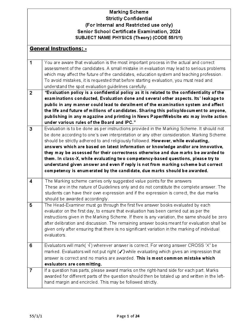
Page 1
Strictly Confidential
(For Internal and Restricted use only)
Senior School Certificate Examination, 2024
SUBJECT NAME PHYSICS (Theory) (CODE 55/1/1)
General Instructions: -
1 You are aware that evaluation is the most important process in the actual and correct
assessment of the candidates. A small mistake in evaluation may lead to serious problems
which may affect the future of the candidates, education system and teaching profession.
To avoid mistakes, it is requested that before starting evaluation, you must read and
understand the spot evaluation guidelines carefully.
2 “Evaluation policy is a confidential policy as it is related to the confidentiality of the
examinations conducted, Evaluation done and several other aspects. Its’ leakage to
public in any manner could lead to derailment of the examination system and affect
the life and future of millions of candidates. Sharing this policy/document to anyone,
publishing in any magazine and printing in News Paper/Website etc may invite action
under various rules of the Board and IPC.”
3 Evaluation is to be done as per instructions provided in the Marking Scheme. It should not
be done according to one’s own interpretation or any other consideration. Marking Scheme
should be strictly adhered to and religiously followed. However, while evaluating,
answers which are based on latest information or knowledge and/or are innovative,
they may be assessed for their correctness otherwise and due marks be awarded to
them. In class-X, while evaluating two competency-based questions, please try to
understand given answer and even if reply is not from marking scheme but correct
competency is enumerated by the candidate, due marks should be awarded.
4 The Marking scheme carries only suggested value points for the answers
These are in the nature of Guidelines only and do not constitute the complete answer. The
students can have their own expression and if the expression is correct, the due marks
should be awarded accordingly.
5 The Head-Examiner must go through the first five answer books evaluated by each
evaluator on the first day, to ensure that evaluation has been carried out as per the
instructions given in the Marking Scheme. If there is any variation, the same should be zero
after delibration and discussion. The remaining answer books meant for evaluation shall be
given only after ensuring that there is no significant variation in the marking of individual
evaluators.
6 Evaluators will mark( √ ) wherever answer is correct. For wrong answer CROSS ‘X” be
marked. Evaluators will not put right (✓)while evaluating which gives an impression that
answer is correct and no marks are awarded. This is most common mistake which
evaluators are committing.
7 If a question has parts, please award marks on the right-hand side for each part. Marks
awarded for different parts of the question should then be totaled up and written in the left-
hand margin and encircled. This may be followed strictly.
55/1/1 Page 1 of 24
Page 2
encircled. This may also be followed strictly.
9 If a student has attempted an extra question, answer of the question deserving more marks
should be retained and the other answer scored out with a note “Extra Question”.
10 No marks to be deducted for the cumulative effect of an error. It should be penalized only
once.
11 A full scale of marks 0 to 70 has to be used. Please do not hesitate to award full marks if
the answer deserves it.
12 Every examiner has to necessarily do evaluation work for full working hours i.e., 8 hours
every day and evaluate 20 answer books per day in main subjects and 25 answer books
per day in other subjects (Details are given in Spot Guidelines).This is in view of the
reduced syllabus and number of questions in question paper.
13 Ensure that you do not make the following common types of errors committed by the
Examiner in the past:-
● Leaving answer or part thereof unassessed in an answer book.
● Giving more marks for an answer than assigned to it.
● Wrong totaling of marks awarded on an answer.
● Wrong transfer of marks from the inside pages of the answer book to the title page.
● Wrong question wise totaling on the title page.
● Wrong totaling of marks of the two columns on the title page.
● Wrong grand total.
● Marks in words and figures not tallying/not same.
● Wrong transfer of marks from the answer book to online award list.
● Answers marked as correct, but marks not awarded. (Ensure that the right tick mark is
correctly and clearly indicated. It should merely be a line. Same is with the X for
incorrect answer.)
● Half or a part of answer marked correct and the rest as wrong, but no marks awarded.
14 While evaluating the answer books if the answer is found to be totally incorrect, it should be
marked as cross (X) and awarded zero (0)Marks.
15 Any un assessed portion, non-carrying over of marks to the title page, or totaling error
detected by the candidate shall damage the prestige of all the personnel engaged in the
evaluation work as also of the Board. Hence, in order to uphold the prestige of all
concerned, it is again reiterated that the instructions be followed meticulously and
judiciously.
16 The Examiners should acquaint themselves with the guidelines given in the “Guidelines for
spot Evaluation” before starting the actual evaluation.
17 Every Examiner shall also ensure that all the answers are evaluated, marks carried over to
the title page, correctly totaled and written in figures and words.
18 The candidates are entitled to obtain photocopy of the Answer Book on request on payment
of the prescribed processing fee. All Examiners/Additional Head Examiners/Head
Examiners are once again reminded that they must ensure that evaluation is carried out
strictly as per value points for each answer as given in the Marking Scheme.
55/1/1 Page 2 of 24
Page 3
CODE :55/1/1
Q.NO. VALUE POINT/EXPECTED ANSWERS MARKS TOTAL
MARKS
Section A
1. (B) Zero 1 1
2. (D) 5.0 ×10⁻² J 1 1
3. (B) 8V 1 1
4. (C) Shrink 1 1
5. (B) ( - 0.8 mN) î 1 1
6. G 1 1
(B)
1000
7. X 1 1
(A)
6
8. (A) I 1 1
9. (C) n f 2 and ni 4 1 1
10. (B) the number of conduction electrons increases 1 1
11. 1 1 1
( C)
3
12. (A) momentum 1 1
13. (D) Assertion (A) is false and reason (R) is also false. 1 1
14. (A) Both Assertion (A) and Reason (R) are true and Reason (R) is the 1 1
correct explanation of the Assertion (A)
15. (A) Both Assertion (A) and Reason (R) are true and Reason (R) is the 1 1
correct explanation of the Assertion (A)
16. (D) Assertion (A) is false and reason (R) is also false. 1 1
Section B
17.
Finding the temperature 2
R R 1 T T ½
R = 2 R [Given]
2 R R 1 T T ½
On solving
T T 250
T 270C or 543K 1
2
55/1/1 Page 3 of 24
Page 4
Finding the wavelength of
(i) Reflected Light 1
(ii) Refracted Light 1
(i)
v=υλ
3×108 = 5×10¹⁴ × λ 1
λ = 600 nm or 6 ×10⁻⁷m
(ii)
medium air
600 nm
medium
1.5 1
= 400 nm or 4×10⁻⁷m
OR
(b)
Calculating the radius of the curved surface 2
1 1 1
( 1)
f R1 R2
1
1 1 1
(1.4 1)
16 R
1 1
0.4
16 R
R = 16 × 0.4
R = 6.4 cm 1 2
19.
Finding the
(i) position of the image formed 1
(ii) magnification of the image 1
½
(i) + =
+ =
On solving
v = - 60 cm ½
55/1/1 Page 4 of 24
Page 5
½
−60
=-( )
−30 ½
= -2
2
20.
Obtaining an expression for λn / λp 2
½
E= => λp =
½
λn = =
√( )
½
= ×
√( )
= √( ) ½
2
21.
Plotting the graph 1
Marking the region where:
(a) resistance is negative ½
(b) Ohm’s law is obeyed ½
1+ ½ + ½
2
55/1/1 Page 5 of 24
Page 6
22.
Calculating
(a) the flux passing through the cube 2
(b) the charge within the cube 1
a) φL = 𝐸⃗ . 𝐴⃗ = - [500 x 0.1] x [(0.1)2] = - 0.5 N m2 C -1 ½
φR = 𝐸 ⃗ . 𝐴⃗ = [500 x 0.2] x [(0.1)2] = 1 N m2 C -1 ½
Net flux = φL + φR = 0.5 N m2 C -1 1
½
b) flux, φ =
charge, q = φ x εo
= 0.5 εo ½
= 4.4 x 10⁻¹² C
3
23.
a)
Defining current density ½
Whether scalar or vector ½
Showing 𝚥⃗ = α 𝐸⃗ 2
Current density is the amount of charge flowing per second per unit area ½
normal to the flow.
Alternatively:
𝑗=
It is a vector quantity. ½
The amount of charge crossing the area A in time ∆t is I ∆t, where I is the
magnitude of the current. Hence, ½
I ∆ t = ne A |vd| ∆t
55/1/1 Page 6 of 24
Page 7
I∆t= τ n ∆t |E|
½
I = |j|A
½
|j| = τ |E|
𝚥⃗ = α 𝐸⃗
OR
b)
Defining Wheatstone bridge 1
Obtaining balancing conditions 2
1
Alternatively:
If the figure is explained in words full credit to be given.
For loop ADBA:
–I1 R1 + I2 R2 + Ig G = 0 (1) ½
For loop CBDC:
I4R4 - I3 R3 - Ig G = 0 (2) ½
For balanced wheatstone bridge, Ig = 0 ½
And by applying Kirchoff’s junction rule to junction D and B,
I1 = I3 & I2 = I4
From eqn (1) and (2)
55/1/1 Page 7 of 24
Page 8
½
=
3
24.
Calculating
a) the speed of the proton 1
b) the magnitude of the acceleration of the proton 1
c) the radius of the path traced by the proton 1
. . ½
a) v = √( )
= 4 x 10⁶ m/s ½
b) acceleration = qvB / m ½
= 8 x 10¹¹ m/s2 ½
c) r = mv / Bq ½
= 20 m ½
3
25.
Deriving an expression for the average power dissipated in series
LCR circuit 2
Obtaining expression for the resonant frequency 1
v = vm sinωt
i = im sin(ωt+φ)
Power, P = v i = ( vm sinωt ) x [ im sin(ωt+φ)] ½
= [ cos φ – cos(2ωt+φ)] (1) ½
The average power over a cycle is given by the average of the two terms in
RHS of eqn (1). It is only the 2nd term which is time dependent. It’s average
is zero. Therefore, ½
P= cos φ
55/1/1 Page 8 of 24
Page 9
OR ½
P = I2 Z cos φ
At resonance, XC = XL
1
= 𝜔𝐿 ½
𝜔𝐶
ω=
√( )
=> υ= ½ 3
√( )
26.
a) Two examples 1
b) (i) Reason for use of short waves bands 1
(ii) Reason for x-ray astronomy from satellites 1
a) (Any Two)
Gamma radiation having wavelength of 10–14 m to 10–15 m, typically
originate from an atomic nucleus.
X-rays are emitted from heavy atoms.
Radio waves are produced by accelerating electrons in a circuit. A
transmitting antenna can most efficiently radiate waves having a
wavelength of about the same size as the antenna. ½+½
b) (i) Ionosphere reflects waves in these bands 1
(ii) Atmosphere absorbs x-rays, while visible and radio waves can
penetrate it 1
Note: Full credit to be given for part (b) for mere attempt. 3
27.
Drawbacks of Rutherford’s atomic model 1
Bohr’s explanation 1
Showing different orbits are not equally spaced 1
Drawbacks:
i) According to classical electromagnetic theory, an accelerating charged
particle emits radiation in the form of electromagnetic waves. The energy of
an accelerating electron should therefore, continuously decrease. The
electron would spiral inward and eventually fall into the nucleus. Thus, such
55/1/1 Page 9 of 24
Page 10
ii) As the electrons spiral inwards, their angular velocities and hence their
frequencies would change continuously. Thus, they would emit a
continuous spectrum, in contradiction to the line spectrum actually
observed. 1
Bohr postulated stable orbits in which electrons do not radiate energy 1
Alternatively:
Bohr’s postulates (Any ONE of the three)
(i) An electron in an atom could revolve in certain stable orbits without the
emission of radiant energy.
(ii) The electron revolves around the nucleus only in those orbits for which
the angular momentum is some integral multiple of h/2π
(iii) An electron might make a transition from one of its specified non-
radiating orbits to another of lower energy. When it does so, a photon is
emitted having energy equal to the energy difference between the initial and
final states.
The radius of the nth orbit is found as
1
rn α n2
Alternatively:
Difference in radius of consecutive orbits is
rn+1 – rn = k [(n+1)2 – n2)]
= k (2n + 1) which depends on n, and is not a constant 3
28.
a) Stating two properties of a nucleus 1
b) Why density of a nucleus is much more than that of an atom 1
c) Showing that density of nuclear matter is same for all nuclei 1
a) (Any TWO)
(i) The nucleus is positively charged
(ii) The nucleus consists of protons and neutrons
(iii) The nuclear density is independent of mass number
(iv) The radius of the nucleus, R = Ro A1/3 ½+½
b) Atoms have large amount of empty spaces. Mass is concentrated in 1
nucleus.
55/1/1 Page 10 of 24
Page 11
= =
=
1
So, density is independent of mass number
3
SECTION D
29. ( ) 1
(i) (A)
(ii) (D) P/2 1
(iii) (B) P 1
(iv) a) (C) 2P 1
OR
b) (A) 6.6 D
4
30.
1
(i) (A)
√
(ii) (B) half cycle of the input signal 1
(iii) (C) One is forward biased and the other is reverse biased at the 1
same time
(iv) a) (B) 50 Hz 1
OR
b) (D)
4
55/1/1 Page 11 of 24
Page 12
31. (a)
(i)
Deriving the expression for potential energy 2
Maximum & Minimum value of potential energy ( ½ + ½ )
(ii) Finding the torque. 2
(i)
The amount of work done in rotating the dipole from θ = 0 to θ = 1 by
the external torque
1
½
W = ext d
o
1 ½
= pE sin d
o
W = pE (cos 0 cos 1 )
½
For 0 and 1
2
= pE (cos cos )
2
U( ) pE cos
½
= - 𝑝⃗.𝐸⃗
(1) Potential energy is maximum when:
p is antiparallel to E ½
Alternatively:
= 180° or π radians
55/1/1 Page 12 of 24
Page 13
p is along to E ½
Alternatively:
= 0°
(ii)
pE sin ½
½
(2aq ) E sin
4
(5 10 3 1 10 12 )103
5 ½
12
4 10 Nm
Direction is along –ve Z direction. ½
OR
(b)
(i) Deriving expression for potential 2½
(ii) New charge on Sphere S1 2½
(i)
2a
-q O +q P 𝚤̂ ½
x
1 q
V
4 0 r ½
V V q V q
55/1/1 Page 13 of 24
Page 14
V
4 0 (x a ) (x a )
q x a x a
4 0 (x 2 a 2 )
q 2a p
V
4 0 (x a ) 4 0 (x 2 a 2 )
22
As p is along x-axis, so
1 p . iˆ ½
V
4 0 (x 2 a 2 )
If x>>a
½
1 p . iˆ
V
4 0 x 2
Alternatively:
1 q q
V ----- (i) ½
4 0 r1 r2
55/1/1 Page 14 of 24
Page 15
r12 r 2 a 2 2ar cos
r22 r 2 a 2 2ar cos
2acos a 2
r12 r 2 1 2
r r
2a cos ½
r 2 1
r
2a cos ½
r2 2
r 1
2
Similarly, r
a
Using binomial theorem & retaining terms upto the first order in ; we
r
obtain
1
1 1 2a cos 2 1 a
1 1 cos ----- (ii)
r1 r r r r
1
1 1 2a cos 2 1 a
1 1 cos ----- (iii)
r2 r r r r
Using equations (i) ,(ii) & (iii) & p = 2qa
q 2a cos p cos
V
4 0 r2 4 0r 2
½
p cos p . rˆ
As r is along the x – axis.
½
p . rˆ p . iˆ
ˆ
V 1 p .i
4 0 x 2
55/1/1 Page 15 of 24
Page 16
Charge on sphere S1 :
Q1 = surface charge density surface Area
2
= 109 4 (1 10 2 )2
= 8 1013 C
½
Charge on sphere S2 :
Q2 = surface charge density surface Area
2
= 109 4 ( 3 102 )2
= 72 1013 C ½
When connected by a thin wire they acquire a common potential V and
the charge remains conserved.
Q1 Q 2 Q1 Q 2 ½
C1V C 2V
Q1 Q 2 (C1 C2 )V
Q1 Q 2
Common potential(V)
C1 C 2
1 1
C1 4 0r1 10 2 10 11 F
9 10 9
9
1 1
C 2 4 0r2 3 10 2 10 11 F
9 10 9
3
13
80 10
V 1.8V
1 1 11
½
10
9 3
1
𝑄 C1V 10 11 1.8
9 ½
𝑄 2 10 12 C
55/1/1 Page 16 of 24
Page 17
Charge on sphere S1 :
Q1 = surface charge density surface Area
2
= 109 4 (1 10 2 )2
= 8 1013 C ½
Charge on sphere S2 :
Q2 = surface charge density surface Area
2
= 109 4 ( 3 102 )2
= 72 1013 C ½
When connected by a thin wire they acquire a common potential V and
the charge remains conserved.
Q1 Q 2 Q1 Q 2 ½
= ½
On solving, 𝑄 2 10 12 C ½
5
32.
(a)
(i) Deriving expression for impedance 2
(ii) Reason 1
(iii) Inductance of coil 2
55/1/1 Page 17 of 24
Page 18
VC + VR =V ½
v m2 v rm
2
v cm
2
vr m im R
vcm im X c
½
v m2 (im R )2 (im Xc )2
i m2 R 2 X c2
=
½
vm
im
R 2 X c2
Impedance Z R 2 X c2 ½
(ii) For direct current (dc), an inductor behaves as a conductor.
As XL = ωL = 2π ν L
1
For dc ν = 0 XL= 0
Alternatively: -
LdI
Induced emf (ε) = -
dt
For dc; dI = 0 ε = 0
55/1/1 Page 18 of 24
Page 19
(iii) R= = 10 Ω
11
v r ms 220
ir ms
R 2 X L2 100 X L2
220 ½
11
100 X L2
220
100 X L2 20
11
Squaring both sides:
100 X L2 400
½
X L2 300 X L 10 3
X L 2 fL 10 3 2 50 L
½
3
L = H
10
OR
(b)
(i) Labelled diagram of step – up transformer 1
Describing working principle ½
Three causes 1½
(ii) Explanation 1
(iii) (1) Output voltage across secondary coil ½
(2) Current in primary coil ½
55/1/1 Page 19 of 24
Page 20
OR
1
The working principle of transformer is mutual induction.
When an alternating voltage is applied to the primary, the resulting current ½
produces an alternating magnetic flux which links the secondary and
induces an emf in it.
Causes of energy losses (Any three)
(a) Flux leakage
(b) Resistance of the windings
(c) Eddy currents
55/1/1 Page 20 of 24
Page 21
(d) Hysteresis
½
(ii) No
½
Current changes correspondingly. So, the input power is equal to the
output power.
(iii)
(1)
Vs N s
VP N P
Ns 3000
Vs VP 90
NP 200
½
Vs 1350 V
(2)
IP Ns
Is NP
½ 5
3000
IP 2 30 A
200
33.
(a)
(i) Graph showing variation of angle of deviation with angle of
incidence 1
Defining angle of minimum deviation 1
sin( A )
n
(ii) Proof of refractive index sin A 1
(iii) (1) Finding angle of minimum deviation 1
(2) Angle of Incidence 1
55/1/1 Page 21 of 24
Page 22
1
Minimum deviation angle is defined as the angle at which angle of 1
incidence is equal to the angle of emergence.
Alternatively
At minimum deviation refracted ray inside the prism becomes parallel
to the base of the prism.
(ii)
At the face XZ :- ½
sin i 1 sin r ----- (1)
r=i+δ [ from diagram] ----- (2)
In ΔXMN ; A+( 90 –i) + 90 =180
55/1/1 Page 22 of 24
Page 23
Putting eq. (3) & (2) in eq. (1)
sin A sin ( A ) ½
sin ( A )
sin A
(iii)
A m
sin
2
(1)
A
sin
2
60 m
sin
2
2 ½
sin 30
60 m 1
sin sin 45
2 2
60 m ½
45 m 30
2
A m ½
(2) i
2
60 30
i
2
i 45 ½
OR
(b)
(i) Statement of Huygens’ Principle ½
Construction of reflected wave front ½
Proof of angle of reflection is equal to angle of incidence 1
(ii) Definition of coherent sources ½
Explanation 1
(iii) Finding the unknown wavelength 1½
(i) Each point of the wavefront is the source of a secondary disturbance and
the wavelets emanating from these points spread out in all directions with
the spread of the wave. Each point of the wavefront is the source of a
55/1/1 Page 23 of 24
Page 24
spread out in all directions with the speed of the wave. These wavelets
emanating from the wavefront are usually referred to as secondary ½
wavelets and if we draw a common tangent to all these spheres, we
obtain the new position of the wavefront at a later time.
½
ΔEAC is congruent to ΔBAC; so i r 1
(ii) Two sources are said to be coherent if the phase difference between ½
them does not change with time.
No, two independent sodium lamps cannot be coherent. ½
Two independent sodium lamps cannot be coherent as the phase between
them does not remain constant with time. ½
(iii)
4 2 5 1
D D
4 5 known ½
d d
5
known
4
5
520
4
= 650 nm 1 5
55/1/1 Page 24 of 24
Page 25
Strictly Confidential
(For Internal and Restricted use only)
Senior School Certificate Examination, 2024
SUBJECT NAME PHYSICS (Theory) (CODE 55/1/2)
General Instructions: -
1 You are aware that evaluation is the most important process in the actual and correct
assessment of the candidates. A small mistake in evaluation may lead to serious problems
which may affect the future of the candidates, education system and teaching profession.
To avoid mistakes, it is requested that before starting evaluation, you must read and
understand the spot evaluation guidelines carefully.
2 “Evaluation policy is a confidential policy as it is related to the confidentiality of the
examinations conducted, Evaluation done and several other aspects. Its’ leakage to
public in any manner could lead to derailment of the examination system and affect
the life and future of millions of candidates. Sharing this policy/document to anyone,
publishing in any magazine and printing in News Paper/Website etc may invite action
under various rules of the Board and IPC.”
3 Evaluation is to be done as per instructions provided in the Marking Scheme. It should not
be done according to one’s own interpretation or any other consideration. Marking Scheme
should be strictly adhered to and religiously followed. However, while evaluating, answers
which are based on latest information or knowledge and/or are innovative, they may
be assessed for their correctness otherwise and due marks be awarded to them. In
class-X, while evaluating two competency-based questions, please try to understand
given answer and even if reply is not from marking scheme but correct competency
is enumerated by the candidate, due marks should be awarded.
4 The Marking scheme carries only suggested value points for the answers
These are in the nature of Guidelines only and do not constitute the complete answer. The
students can have their own expression and if the expression is correct, the due marks
should be awarded accordingly.
5 The Head-Examiner must go through the first five answer books evaluated by each
evaluator on the first day, to ensure that evaluation has been carried out as per the
instructions given in the Marking Scheme. If there is any variation, the same should be zero
after delibration and discussion. The remaining answer books meant for evaluation shall be
given only after ensuring that there is no significant variation in the marking of individual
evaluators.
6 Evaluators will mark( √ ) wherever answer is correct. For wrong answer CROSS ‘X” be
marked. Evaluators will not put right (✓)while evaluating which gives an impression that
answer is correct and no marks are awarded. This is most common mistake which
evaluators are committing.
7 If a question has parts, please award marks on the right-hand side for each part. Marks
awarded for different parts of the question should then be totaled up and written in the left-
hand margin and encircled. This may be followed strictly.
8 If a question does not have any parts, marks must be awarded in the left-hand margin and
encircled. This may also be followed strictly.
55/1/2 Page 1 of 22
Page 26
should be retained and the other answer scored out with a note “Extra Question”.
10 No marks to be deducted for the cumulative effect of an error. It should be penalized only
once.
11 A full scale of marks 0 to 70 has to be used. Please do not hesitate to award full marks if
the answer deserves it.
12 Every examiner has to necessarily do evaluation work for full working hours i.e., 8 hours
every day and evaluate 20 answer books per day in main subjects and 25 answer books
per day in other subjects (Details are given in Spot Guidelines).This is in view of the
reduced syllabus and number of questions in question paper.
13 Ensure that you do not make the following common types of errors committed by the
Examiner in the past:-
● Leaving answer or part thereof unassessed in an answer book.
● Giving more marks for an answer than assigned to it.
● Wrong totaling of marks awarded on an answer.
● Wrong transfer of marks from the inside pages of the answer book to the title page.
● Wrong question wise totaling on the title page.
● Wrong totaling of marks of the two columns on the title page.
● Wrong grand total.
● Marks in words and figures not tallying/not same.
● Wrong transfer of marks from the answer book to online award list.
● Answers marked as correct, but marks not awarded. (Ensure that the right tick mark is
correctly and clearly indicated. It should merely be a line. Same is with the X for
incorrect answer.)
● Half or a part of answer marked correct and the rest as wrong, but no marks awarded.
14 While evaluating the answer books if the answer is found to be totally incorrect, it should be
marked as cross (X) and awarded zero (0)Marks.
15 Any un assessed portion, non-carrying over of marks to the title page, or totaling error
detected by the candidate shall damage the prestige of all the personnel engaged in the
evaluation work as also of the Board. Hence, in order to uphold the prestige of all
concerned, it is again reiterated that the instructions be followed meticulously and
judiciously.
16 The Examiners should acquaint themselves with the guidelines given in the “Guidelines for
spot Evaluation” before starting the actual evaluation.
17 Every Examiner shall also ensure that all the answers are evaluated, marks carried over to
the title page, correctly totaled and written in figures and words.
18 The candidates are entitled to obtain photocopy of the Answer Book on request on payment
of the prescribed processing fee. All Examiners/Additional Head Examiners/Head
Examiners are once again reminded that they must ensure that evaluation is carried out
strictly as per value points for each answer as given in the Marking Scheme.
55/1/2 Page 2 of 22
Page 27
CODE :55/1/2
Q.NO. VALUE POINT/EXPECTED ANSWERS MARKS TOTAL
MARKS
Section A
1. (B) Zero 1 1
2. (A) 1 1 1
3. (D) 2E and 4r 1 1
4. 1 1 1
(D)
4
5. (B) (-0.8 mN) î 1 1
6. G 1 1
(B)
1000
7. (C) 4πµV 1 1
8. (A) In the same phase and perpendicular to each other 1 1
9. 1 1 1
(C)
3
10. (A) momentum 1 1
11. ( B) the number of conduction electrons increases. 1 1
12. (C) n f 2 and ni 4 1 1
13. (D) Assertion (A) is false and reason (R) is also false.. 1 1
14. (A) Both Assertion (A) and Reason (R) are true and Reason (R) is the 1 1
correct explanation of the Assertion (A)
15. (D) Assertion is false and Reason ( R) is also false. 1 1
16. (A) Both Assertion (A) and Reason(R) are true and Reason( R ) is the 1 1
correct explanation of the Assertion (A)
Section B
17.
Finding the value of R 2
9
i ½
R 1
As potential difference across 6V is zero;
9 ½
6 – ir = 0 6 0.8 0
R 1
On solving;
R= 0.2Ω 1 2
18.
Obtaining an expression for λn / λp 2
55/1/2 Page 3 of 22
Page 28
E= => λp =
½
λn = =
√( )
½
= ×
√( )
= √( ) ½
2
19.
(a) Finding the wavelength of
(i) Reflected Light 1
(ii) Refracted Light 1
(i)
v=υλ
3×108 = 5×10¹⁴ × λ 1
λ = 600 nm or 6 ×10⁻⁷m
(ii)
medium air
600 nm
medium
1.5 1
= 400 nm or 4×10⁻⁷m
OR
(b)
Calculating the radius of the curved surface 2
1 1 1
( 1)
f R1 R2
1 1 1 1
(1.4 1)
16 R
1 1
0.4
16 R
R = 16 × 0.4
R = 6.4 cm 1 2
55/1/2 Page 4 of 22
Page 29
Finding the
(i) position of the image formed 1
(ii) magnification of the image 1
½
(i) + =
+ =
On solving ½
v = - 60 cm
½
(ii) m = -
−60 ½
=-( ) = -2
−30 2
21. Variation of conductivity of an intrinsic semiconductor with
temperature and it’s explanation ½+½
Graph showing variation of conductivity with temperature 1
Conductivity will increase. ½
As the temperature increase , more thermal energy becomes available to
these electrons and some of these electrons may break -away ( becoming ½
free electrons contributing to conduction)
1
2
55/1/2 Page 5 of 22
Page 30
22.
Nature of Q1 1
Value of Q1 2
Nature of Q1 will be negative. 1
Let , Q1 = Q3 = q
1 qQ2 qq Q2 q ½
=0
4 0 d 2d d
1 q2
qQ Q2 q 0
4 0 d
2
2
2 ½
q
2qQ2 0
2
q2
2qQ2
2
Q1 = q 4Q2 1
3
23. a)
Defining current density ½
Whether scalar or vector ½
Showing 𝚥⃗ = α 𝐸⃗ 2
Current density is the amount of charge flowing per second per unit area
normal to the flow. ½
Alternatively:
𝑗=
It is a vector quantity. ½
55/1/2 Page 6 of 22
Page 31
magnitude of the current. Hence, ½
I ∆ t = ne A |vd| ∆t
½
I∆t= τ n ∆t |E|
½
I = |j|A
½
|j| = τ |E|
𝚥⃗ = α 𝐸⃗
OR
b)
Defining Wheatstone bridge 1
Obtaining balancing conditions 2
1
Alternatively:
If the figure is explained in words full credit to be given.
For loop ADBA:
–I1 R1 + I2 R2 + Ig G = 0 (1)
½
For loop CBDC:
I4 R4 - I3 R3 - Ig G = 0 (2) ½
For balanced wheatstone bridge, Ig = 0 ½
And by applying Kirchoff’s junction rule to junction D and B,
I1 = I3 & I2 = I4
55/1/2 Page 7 of 22
Page 32
= and =
= ½
3
24.
(a) Finding the work done to turn the magnet
(i) normal to the field direction 1
(ii) opposite to the field direction 1
(b) Torque on the magnet for case (i) and (ii) ½+½
(a)
(i)
W = -mB( Cosθ2- Cosθ1)
= - mB( Cos90°- Cos0°)
= mB
W = 2.5 ×0.32
W = 0.8 J 1
(ii)
W = -mB( Cos180°- Cos0°)
= 2 mB
= 2× 0.8 1
W = 1.6 J
(b)
(i)
τ = mB sin θ ½
= 0.8 Nm
(ii)
τ=0 ½
3
25.
(a) Explaining the phenomenon 1
(b) Two Factors on which current depends 1
(c) Direction of current in coil Q when
(i) R is increased ½
(ii) R is decreased ½
55/1/2 Page 8 of 22
Page 33
When an alternating voltage is applied to the primary, the resulting
1
current produces an alternating magnetic flux which links the
secondary and induces an emf in it.
(b)
Factors on which the current produced in coil Q depends will be: (Any two)
(i) Number of turns in coil P and Q
(ii) Current flowing through coil P. ½+½
(iii) Resistance of coil Q.
(iv) Mutual Induction between the two coils.
(c) The direction of current through coil Q: ½
(i) Clockwise when R is increased. ½
(ii) Anticlockwise when R is decreased. 3
26.
Drawbacks of Rutherford’s atomic model 1
Bohr’s explanation 1
Showing different orbits are not equally spaced 1
Drawbacks:
i) According to classical electromagnetic theory, an accelerating charged
particle emits radiation in the form of electromagnetic waves. The energy of
an accelerating electron should therefore, continuously decrease. The
electron would spiral inward and eventually fall into the nucleus. Thus, such
an atom cannot be stable.
ii) As the electrons spiral inwards, their angular velocities and hence their
frequencies would change continuously. Thus, they would emit a
continuous spectrum, in contradiction to the line spectrum actually 1
observed.
Bohr postulated stable orbits in which electrons do not radiate energy 1
Alternatively:
Bohr’s postulates (Any ONE of the three)
(i) An electron in an atom could revolve in certain stable orbits without the
emission of radiant energy.
(ii) The electron revolves around the nucleus only in those orbits for which
the angular momentum is some integral multiple of h/2π
(iii) An electron might make a transition from one of its specified non-
radiating orbits to another of lower energy. When it does so, a photon is
emitted having energy equal to the energy difference between the initial and
final states.
55/1/2 Page 9 of 22
Page 34
1
rn α n2
Alternatively:
Difference in radius of consecutive orbits is
rn+1 – rn = k [(n+1)2 – n2)]
= k (2n + 1) which depends on n, and is not a constant 3
27.
a) Two examples 1
b) (i) Reason for use of short waves bands 1
(ii) Reason for x-ray astronomy from satellites 1
a) (Any Two)
Gamma radiation having wavelength of 10–14 m to 10–15 m, typically
originate from an atomic nucleus.
X-rays are emitted from heavy atoms.
Radio waves are produced by accelerating electrons in a circuit. A
transmitting antenna can most efficiently radiate waves having a
wavelength of about the same size as the antenna. ½+½
b) (i) Ionosphere reflects waves in these bands 1
(ii) Atmosphere absorbs x-rays, while visible and radio waves can
penetrate it. 1
Note: Full credit to be given for part (b) for mere attempt.
3
28.
(a) Two properties of nuclear force 1
(b) Plotting graph between potential energy as a function of
separation. 1
Two important conclusions. 1
(a) Properties of nuclear forces (Any two) :
(i) The nuclear force is much stronger than the Coulomb force
acting between charges or the gravitational forces between
their masses.
(ii) The nuclear force between two nucleons falls rapidly to zero
as their distance becomes more than a few femtometres.
(iii) The nuclear force between neutron- neutron, proton- neutron
55/1/2 Page 10 of 22
Page 35
(iv) The nuclear force is charge independent. ½+½
(b)
1
Note: Full credit to be given if values are not marked on the graph.
Conclusions:-
(i) The potential energy is minimum at a distance r .
(ii) The force between the nucleons is attractive for distances larger
than r and repulsive if they are separated by distance less than r . ½+½
3
Section D
29.
1
(i) (A)
√
(ii) (B) half cycle of the input signal 1
(iii) (C) One is forward biased and the other is reverse biased at the 1
same time
(iv) a) (B) 50 Hz 1
OR
b) (D)
4
30. ( )
(i) (A) 1
(ii) (D) P/2
(iii) (B) P 1
(iv) a) (C) 2P 1
OR
b) (A) 6.6 D 1
4
55/1/2 Page 11 of 22
Page 36
31. (a)
(i) Graph showing variation of angle of deviation with angle of
incidence 1
Defining angle of minimum deviation 1
sin( A )
n
(ii) Proof of refractive index sin A 1
(iii) (1) Finding angle of minimum deviation 1
(2) Angle of Incidence 1
(i)
1
Minimum deviation angle is defined as the angle at which angle of 1
incidence is equal to the angle of emergence.
Alternatively
At minimum deviation refracted ray inside the prism becomes parallel to the
base of the prism.
55/1/2 Page 12 of 22
Page 37
At the face XZ :- ½
sin i 1 sin r ----- (1)
r=i+δ [ from diagram] ----- (2)
In ΔXMN ; A+( 90 –i) + 90 =180
A=i ----- (3) ½
Putting eq. (3) & (2) in eq. (1)
sin A sin ( A )
sin ( A )
sin A
(iii)
A m
sin
(1) 2
A
sin
2
60 m ½
sin
2
2
sin 30
60 m 1
sin sin 45
2 2
60 m ½
45 m 30
2
A m ½
(2) i
2
60 30
i
2 ½
i 45
55/1/2 Page 13 of 22
Page 38
(b)
(i) Statement of Huygens’ Principle ½
Construction of reflected wave front ½
Proof of angle of reflection is equal to angle of incidence 1
(ii) Definition of coherent sources ½
Explanation 1
(iii) Finding the unknown wavelength 1½
(i) Each point of the wavefront is the source of a secondary
disturbance and the wavelets emanating from these points spread
out in all directions with the spread of the wave. Each point of
the wavefront is the source of a secondary disturbance and the
wavelets emanating from these points spread out in all directions ½
with the speed of the wave. These wavelets emanating from the
wavefront are usually referred to as secondary wavelets and if
we draw a common tangent to all these spheres, we obtain the
new position of the wavefront at a later time.
½
ΔEAC is congruent to ΔBAC; so i r 1
(ii) Two sources are said to be coherent if the phase difference between ½
them does not change with time.
No, two independent sodium lamps cannot be coherent. ½
Two independent sodium lamps cannot be coherent as the phase between
them does not remain constant with time. ½
(iii)
4 2 5 1
D D
4 5 known ½
d d
55/1/2 Page 14 of 22
Page 39
known
4
5 1
520 5
4
= 650 nm
32. (a)
(i)
Deriving the expression for potential energy 2
Maximum & Minimum value of potential energy (½+½)
(ii) Finding the torque. 2
(i)
The amount of work done in rotating the dipole from θ = 0 to θ = 1 by
the external torque
1
½
W = ext d
o
1
= pE sin d
o
W = pE (cos 0 cos 1 ) ½
½
For 0 & 1
2
= pE (cos cos )
2
U( ) pE cos
½
= - 𝑝⃗.𝐸⃗
(1) Potential energy is maximum when:
p is antiparallel to E ½
55/1/2 Page 15 of 22
Page 40
= 180° or π radians
(2) Potential energy is minimum when:
p is along to E ½
Alternatively:
= 0°
(ii)
½
pE sin ½
(2aq ) E sin
4
(5 10 3 1 10 12 )103
5
½
4 10 12 Nm
Direction is along –ve Z direction. ½
OR
(b)
(i) Deriving expression for potential 2½
(ii) New charge on Sphere S1 2½
(i)
2a
½
-q O +q P 𝚤̂
x
55/1/2 Page 16 of 22
Page 41
V ½
4 0 r
V V q V q
1 q q
V
4 0 (x a ) (x a )
½
q x a x a
4 0 (x 2 a 2 )
q 2a p
V ½
4 0 (x a ) 4 0 (x 2 a 2 )
2 2
As p is along x-axis, so
1 p . iˆ
V
4 0 (x 2 a 2 )
If x>>a ½
1 p . iˆ
V
4 0 x 2
Alternatively:
1 q q
V ----- (i) ½
4 0 r1 r2
By geometry
r12 r 2 a 2 2ar cos
r22 r 2 a 2 2ar cos
2acos a 2
r r 1
1
2 2
2
r r
55/1/2 Page 17 of 22
Page 42
r 2 1
r
2a cos
r22 r 2 1
Similarly, r
a
Using binomial theorem & retaining terms upto the first order in ;
r
we obtain
1
1 1 2a cos 2 1 a
1 1 cos ----- (ii) ½
r1 r r r r
1
1 1 2a cos 2 1 a
1 1 cos ----- (iii) ½
r2 r r r r
Using equations (i) ,(ii) & (iii) & p = 2qa
q 2a cos p cos ½
V
4 0 r2 4 0r 2
p cos p . rˆ
As r is along the x – axis.
p . rˆ p . iˆ
ˆ
V 1 p .i ½
4 0 x 2
(ii)
Charge on sphere S1 :
Q1 = surface charge density surface Area
2
= 109 4 (1 10 2 )2
½
13
= 8 10 C
Charge on sphere S2 :
Q2 = surface charge density surface Area
2
= 109 4 ( 3 102 )2
13
= 72 10 C ½
When connected by a thin wire they acquire a common potential V
and the charge remains conserved. ½
Q1 Q2 Q1 Q2
C1V C 2V
Q1 Q 2 (C1 C2 )V
55/1/2 Page 18 of 22
Page 43
Common potential(V)
C1 C 2
1 1
C1 4 0r1 10 2 10 11 F
9 10 9
9
1 1
C 2 4 0r2 3 10 2 10 11 F
9 10 9
3
13
80 10 ½
V 1.8V
1 1 11
10
9 3
1
𝑄 C1V 10 11 1.8
9
𝑄 2 10 12 C ½
Alternatively:
Charge on sphere S1 :
Q1 = surface charge density surface Area
2
= 109 4 (1 10 2 )2
= 8 10 C13 ½
Charge on sphere S2 :
Q2 = surface charge density surface Area
2
= 109 4 ( 3 102 )2
13
= 72 10 C ½
When connected by a thin wire they acquire a common potential V
and the charge remains conserved. ½
Q1 Q2 Q1 Q2
½
=
½
On solving, 𝑄 2 10 12 C
5
33. (a)
(i) Deriving expression for impedance 2
(ii) Reason 1
(iii) Inductance of coil 2
55/1/2 Page 19 of 22
Page 44
½
VC + VR = V
v m2 v rm
2
v cm
2
vr m im R
vcm im X c
v m2 (im R )2 (im Xc )2 ½
i 2
m
R X
2 2
c
=
vm ½
im
R X c2
2
½
Impedance Z R 2 X c2
(ii) For direct current (dc), an inductor behaves as a conductor.
As XL = ωL = 2π ν L 1
For dc ν = 0 XL= 0
Alternatively: -
LdI
Induced emf (ε) = -
dt
For dc; dI = 0 ε = 0
110 ½
(iii) R = = 10 Ω
11
v r ms 220
ir ms
R 2 X L2 100 X L2
220
11 ½
100 X L2
220
100 X L2 20
11
Squaring both sides:
100 X L2 400
55/1/2 Page 20 of 22
Page 45
X L 2 fL 10 3 2 50 L
3 ½
L = H
10
OR
(b)
(i) Labelled diagram of step – up transformer 1
Describing working principle ½
Three causes 1½
(ii) Explanation 1
(iii) (1) Output voltage across secondary coil ½
(2) Current in primary coil ½
(i)
OR
1
55/1/2 Page 21 of 22
Page 46
When an alternating voltage is applied to the primary, the resulting
current produces an alternating magnetic flux which links the
½
secondary and induces an emf in it.
Causes of energy losses (Any three)
(a) Flux leakage
(b) Resistance of the windings
(c) Eddy currents
½+½+½
(d) Hysteresis
(ii) No ½
Current changes correspondingly. So, the input power is equal to the
output power. ½
(iii)
(1)
Vs N s
VP N P
N 3000
Vs s VP 90
NP 200
Vs 1350 V ½
(2)
IP Ns
Is NP
3000 ½
IP 2 30 A
200
5
55/1/2 Page 22 of 22
Page 47
Strictly Confidential
(For Internal and Restricted use only)
Senior School Certificate Examination, 2024
SUBJECT NAME PHYSICS (Theory) ( CODE 55/1/3)
General Instructions: -
1 You are aware that evaluation is the most important process in the actual and correct
assessment of the candidates. A small mistake in evaluation may lead to serious problems which
may affect the future of the candidates, education system and teaching profession. To avoid
mistakes, it is requested that before starting evaluation, you must read and understand the spot
evaluation guidelines carefully.
2 “Evaluation policy is a confidential policy as it is related to the confidentiality of the
examinations conducted, Evaluation done and several other aspects. Its’ leakage to
public in any manner could lead to derailment of the examination system and affect the
life and future of millions of candidates. Sharing this policy/document to anyone,
publishing in any magazine and printing in News Paper/Website etc may invite action
under various rules of the Board and IPC.”
3 Evaluation is to be done as per instructions provided in the Marking Scheme. It should not be
done according to one’s own interpretation or any other consideration. Marking Scheme should
be strictly adhered to and religiously followed. However, while evaluating, answers which are
based on latest information or knowledge and/or are innovative, they may be assessed for
their correctness otherwise and due marks be awarded to them. In class-X, while
evaluating two competency-based questions, please try to understand given answer and
even if reply is not from marking scheme but correct competency is enumerated by the
candidate, due marks should be awarded.
4 The Marking scheme carries only suggested value points for the answers
These are in the nature of Guidelines only and do not constitute the complete answer. The
students can have their own expression and if the expression is correct, the due marks should
be awarded accordingly.
5 The Head-Examiner must go through the first five answer books evaluated by each evaluator on
the first day, to ensure that evaluation has been carried out as per the instructions given in the
Marking Scheme. If there is any variation, the same should be zero after delibration and
discussion. The remaining answer books meant for evaluation shall be given only after ensuring
that there is no significant variation in the marking of individual evaluators.
6 Evaluators will mark( √ ) wherever answer is correct. For wrong answer CROSS ‘X” be marked.
Evaluators will not put right (✓)while evaluating which gives an impression that answer is
correct and no marks are awarded. This is most common mistake which evaluators are
committing.
7 If a question has parts, please award marks on the right-hand side for each part. Marks awarded
for different parts of the question should then be totaled up and written in the left-hand margin
and encircled. This may be followed strictly.
8 If a question does not have any parts, marks must be awarded in the left-hand margin and
encircled. This may also be followed strictly.
55/1/3 Page 1 of 25
Page 48
should be retained and the other answer scored out with a note “Extra Question”.
10 No marks to be deducted for the cumulative effect of an error. It should be penalized only once.
11 A full scale of marks ___0 to 70_____(example 0 to 80/70/60/50/40/30 marks as given in
Question Paper) has to be used. Please do not hesitate to award full marks if the answer
deserves it.
12 Every examiner has to necessarily do evaluation work for full working hours i.e., 8 hours every
day and evaluate 20 answer books per day in main subjects and 25 answer books per day in
other subjects (Details are given in Spot Guidelines).This is in view of the reduced syllabus and
number of questions in question paper.
13 Ensure that you do not make the following common types of errors committed by the Examiner in
the past:-
● Leaving answer or part thereof unassessed in an answer book.
● Giving more marks for an answer than assigned to it.
● Wrong totaling of marks awarded on an answer.
● Wrong transfer of marks from the inside pages of the answer book to the title page.
● Wrong question wise totaling on the title page.
● Wrong totaling of marks of the two columns on the title page.
● Wrong grand total.
● Marks in words and figures not tallying/not same.
● Wrong transfer of marks from the answer book to online award list.
● Answers marked as correct, but marks not awarded. (Ensure that the right tick mark is
correctly and clearly indicated. It should merely be a line. Same is with the X for incorrect
answer.)
● Half or a part of answer marked correct and the rest as wrong, but no marks awarded.
14 While evaluating the answer books if the answer is found to be totally incorrect, it should be
marked as cross (X) and awarded zero (0)Marks.
15 Any un assessed portion, non-carrying over of marks to the title page, or totaling error detected
by the candidate shall damage the prestige of all the personnel engaged in the evaluation work
as also of the Board. Hence, in order to uphold the prestige of all concerned, it is again reiterated
that the instructions be followed meticulously and judiciously.
16 The Examiners should acquaint themselves with the guidelines given in the “Guidelines for
spot Evaluation” before starting the actual evaluation.
17 Every Examiner shall also ensure that all the answers are evaluated, marks carried over to the
title page, correctly totaled and written in figures and words.
18 The candidates are entitled to obtain photocopy of the Answer Book on request on payment of
the prescribed processing fee. All Examiners/Additional Head Examiners/Head Examiners are
once again reminded that they must ensure that evaluation is carried out strictly as per value
points for each answer as given in the Marking Scheme.
55/1/3 Page 2 of 25
Page 49
CODE :55/1/3
Q.NO. VALUE POINT/EXPECTED ANSWERS MARKS TOTAL
MARKS
SECTION A
1. (B) Zero 1 1
2. (B) B 1 1
3. (B) E and j both are along –x direction 1 1
4. a
2 1 1
(C)
b
5. G 1 1
(B)
1000
6. (B) (-0.8 mN) î 1 1
7. (D) 2200V - 50 HZ 1 1
8. (C) J.C. Bose 1 1
9. (A) momentum 1 1
10. 1 1 1
(C)
3
11. ( C) n f 2 and ni 4 1 1
12. (B) the number of conduction electrons increases 1 1
13. (A) Both Assertion (A) and Reason (R) are true and Reason (R) is the 1 1
correct explanation of the Assertion (A)
14. (D) Assertion (A) is false and reason (R) is also false. 1 1
15. (A) Assertion(A) is true , Reason (R) is true and Reason (R) is correct 1 1
explanation of the Assertion (A)
16. (D) Assertion (A) is false and Reason (R) is also false. 1 1
SECTION B
17.
Calculating the percentage 2
increase in the resistance
As the wire is uniformly stretched;
lA ½
Al Al A
1.25l
4
A = A
5
l 1.25l
R
A 4
A
5
25 1
R R
16
55/1/3 Page 3 of 25
Page 50
% increase = 100
R
25 ½
= 1 100 56.25%
16 2
18.
Finding the
(i) position of the image formed 1
(ii) magnification of the image 1
½
(i) + =
+ =
On solving ½
v = - 60 cm
½
(ii) m = -
−60 ½
=-( ) = -2
−30 2
19.
Obtaining an expression for λn / λp 2
½
E= => λp =
½
λn = =
√( )
½
= ×
√( )
= √( ) ½
2
20.
Finding the wavelength of
(i) Reflected Light 1
(ii) Refracted Light 1
55/1/3 Page 4 of 25
Page 51
(i)
v=υλ
3×108 = 5×10¹⁴ × λ 1
λ = 600 nm or 6 ×10⁻⁷m
(ii)
medium air
600 nm
medium
1.5 1
= 400 nm or 4×10⁻⁷m
OR
(b)
Calculating the radius of the curved surface 2
1 1 1
( 1)
f R1 R2
1
1 1 1
(1.4 1)
16 R
1 1
0.4
16 R
R = 16 × 0.4
R = 6.4 cm 1 2
21.
Differentiating between diffusion & drift current 1
Explaining their role in p-n junction 1
Diffusion current: It is due to the flow of majority charge carriers. 1
Drift current: It is due to the flow of minority charge carriers.
Due to the concentration gradient across p- , and n- sides, holes diffuse from
p- side to n- side & electrons diffuse from n-side to p- side. This motion of
charge carriers gives rise to diffusion current across the junction.
Due to the positive space- charge region on n-side and negative space – 1
charge region on p-side, an electric field directed from positive charge
towards negative charge develops. Due to this field, motion of charge
carriers comes into play giving rise to drift current.
2
55/1/3 Page 5 of 25
Page 52
22.
Calculating the amount of work done 3
A A
C ; C
d d
C d 1
C 20
C d 5
1
C = 4pF
Work done = change in energy
1 Q2 1 Q2
=
2 C 2 C
Q2 1 1 1
= 1012
2 4 20
On solving ;
8
Work done = J
5 1
1.6 J 3
23.
a)
Defining current density ½
Whether scalar or vector ½
Showing 𝚥⃗ = α 𝐸⃗ 2
Current density is the amount of charge flowing per second per unit area ½
normal to the flow.
Alternatively:
𝑗=
It is a vector quantity. ½
The amount of charge crossing the area A in time ∆t is I ∆t, where I is the
magnitude of the current. Hence,
55/1/3 Page 6 of 25
Page 53
I∆t= τ n ∆t |E|
½
I = |j|A
½
|j| = τ |E| ½
𝚥⃗ = α 𝐸⃗
OR
b)
Defining Wheatstone bridge 1
Obtaining balancing conditions 2
1
Alternatively:
If the figure is explained in words full credit to be given.
For loop ADBA:
–I1 R1 + I2 R2 + Ig G = 0 (1) ½
For loop CBDC:
I4 R4 - I3 R3 - Ig G = 0 (2) ½
For balanced wheatstone bridge, Ig = 0
And by applying Kirchoff’s junction rule to junction D and B, ½
I1 = I3 & I2 = I4
55/1/3 Page 7 of 25
Page 54
= and =
=
½
3
24.
Calculating
(a) Net force 1
(b) Torque 1
(c ) Average force 1
(a)
Net force = zero
By symmetry, force on each element of the coil is equal and 1
opposite to the force on the diametrically opposite element of the
coil. Hence, the net force is zero.
Alternatively :
df1 Idl B
df 2 Idl B
F1 F2
On coil magnetic force are equal
and opposite, so they will cancel
out each other.
(b)
Torque on the coil.
m B
m B sin m B
mB sin 0 0
1
τ= 0
(c)
f avg e(v d B) ½
= e v d B sin 90
= e vd B
I n e A vd
55/1/3 Page 8 of 25
Page 55
vd
ne A
I
f avg e B
ne A
IB
=
nA
4 0.5
=
10 0.2 10 4
28
½
= 10-23 N
3
25.
(a)
(i) Graph showing variation of R with frequency ½
(ii) Graph showing variation of capacitive reactance
with frequency ½
(iii) Graph showing variation of Inductive reactance with
frequency ½
(b) Anwer and Justification ½ +1
(a) (i) R
½
ν
(ii)
½
(iii)
½
55/1/3 Page 9 of 25
Page 56
VL and VC are in opposite phase. 1
3
26.
a) Stating two properties of a nucleus 1
b) Why density of a nucleus is much more than that of an atom 1
c) Showing that density of nuclear matter is same for all nuclei 1
a) (Any TWO)
(i) The nucleus is positively charged
(ii) The nucleus consists of protons and neutrons
(iii) The nuclear density is independent of mass number
(iv) The radius of the nucleus, R = Ro A1/3 ½+½
b) Atoms have large amount of empty spaces. Mass is concentrated in 1
nucleus.
c) Density = Mass / Volume
= =
=
So, density is independent of mass number. 1
3
27.
Statement of three postulates ½+½+½
Showing that frequency, ν ≅ 1½
n3
Bohr’s postulates:-
(i) An electron in an atom could revolve in certain stable orbits without the
emission of radiant energy.
(ii) The electron revolves around the nucleus only in those orbits for which
the angular momentum is some integral multiple of h/2π
55/1/3 Page 10 of 25
Page 57
radiating orbits to another of lower energy. When it does so, a photon is
emitted having energy equal to the energy difference between the initial and ½ + ½ +½
final states.
hν = Ei – Ef ------- (i)
1 ½
En 2
n
1 1
En En1 k 2
(n 1) n
2
n 2 n 2 1 2n
k
n 4 2n3 n 2
2n 1
k 4
n 2n 3 n 2
For large n , 2n-1 2n
n2 [n2- 2n+1] n4
2 n 2k
En En1 k 1
n 4 n3 ----- (ii)
From equation (i) and (ii)
ν
3
28.
a) Two examples 1
b) (i) Reason for use of short waves bands 1
(ii) Reason for x-ray astronomy from satellites 1
a) (Any Two)
Gamma radiation having wavelength of 10–14 m to 10–15 m, typically
originate from an atomic nucleus.
X-rays are emitted from heavy atoms.
Radio waves are produced by accelerating electrons in a circuit. A
transmitting antenna can most efficiently radiate waves having a
wavelength of about the same size as the antenna. ½+½
b) (i) Ionosphere reflects waves in these bands 1
(ii) Atmosphere absorbs x-rays, while visible and radio waves can
penetrate it 1
Note: Full credit to be given for part (b) for mere attempt. 3
55/1/3 Page 11 of 25
Page 58
29. ( ) 1
(i) (A)
(ii) (D) P/2 1
(iii) (B) P 1
(iv) a) (C) 2P 1
OR
b) (A) 6.6 D
4
30. 1
(i) (A)
√
(ii) (B) half cycle of the input signal 1
(iii) (C) One is forward biased and the other is reverse biased at the 1
same time
(iv) a) (B) 50 Hz
1
OR
b) (D)
4
SECTION E
31.
(a) (i) Deriving expression for impedance 2
(ii) Reason 1
(iii) Inductance of coil 2
55/1/3 Page 12 of 25
Page 59
½
VC + VR =V
v m2 v rm
2
v cm
2
vr m im R
vcm im X c
½
vm2 (im R )2 (im Xc )2
i m2 R 2 X c2
=
½
vm
im
R 2 X c2
½
Impedance Z R 2 X c2
(ii) For direct current (dc), an inductor behaves as a conductor.
As XL = ωL = 2π ν L 1
For dc ν = 0 XL= 0
Alternatively: -
LdI
Induced emf (ε) = -
dt
For dc; dI = 0 ε = 0
110 ½
(iii) R= = 10 Ω
11
55/1/3 Page 13 of 25
Page 60
ir ms
R X
2 2
L 100 X L2
½
220
11
100 X L2
220
100 X L2 20
11
Squaring both sides:
100 X L2 400
½
X L2 300 X L 10 3
X L 2 fL 10 3 2 50 L
3 ½
L = H
10
OR
(b)
(i) Labelled diagram of step – up transformer 1
Describing working principle ½
Three causes 1½
(ii) Explanation 1
(iii) (1) Output voltage across secondary coil ½
(2) Current in primary coil ½
55/1/3 Page 14 of 25
Page 61
OR
1
The working principle of transformer is mutual induction.
When an alternating voltage is applied to the primary, the resulting current
produces an alternating magnetic flux which links the secondary and ½
induces an emf in it.
Causes of energy losses (Any three)
(a) Flux leakage
(b) Resistance of the windings
(c) Eddy currents
(d) Hysteresis ½+½+½
55/1/3 Page 15 of 25
Page 62
Current changes correspondingly. So, the input power is equal to the
output power. ½
(iii)
(1)
Vs N s
VP N P
Ns 3000
Vs VP 90
NP 200
½
Vs 1350 V
(2)
IP Ns
Is NP
½
3000
IP 2 30 A
200
5
32. (a)
(i)
Deriving the expression for potential energy 2
Maximum & Minimum value of potential energy (½+½)
(ii) Finding the torque. 2
55/1/3 Page 16 of 25
Page 63
The amount of work done in rotating the dipole from θ = 0 to θ = 1 by
the external torque
1
½
W = ext d
o
1 ½
= pE sin d
o
W = pE (cos 0 cos 1 )
½
For 0 & 1
2
= pE (cos cos )
2
U( ) pE cos
½
= - 𝑝⃗.𝐸⃗
(1) Potential energy is maximum when:
p is antiparallel to E ½
Alternatively:
= 180° or π radians
(2) Potential energy is minimum when:
½
p is along to E
Alternatively:
= 0°
55/1/3 Page 17 of 25
Page 64
½
pE sin ½
(2aq ) E sin
4
(5 10 3 1 10 12 )103 ½
5
4 10 12 Nm ½
Direction is along –ve Z direction.
OR
(b)
(i) Deriving expression for potential 2½
(ii) New charge on Sphere S1 2½
(i)
2a
-q O +q P 𝚤̂ ½
x
1 q ½
V
4 0 r
V V q V q
1 q q ½
V
4 0 (x a ) (x a )
55/1/3 Page 18 of 25
Page 65
4 0 (x 2 a 2 )
½
q 2a p
V
4 0 (x a ) 4 0 (x 2 a 2 )
2 2
As p is along x-axis, so
1 p . iˆ
V
4 0 (x 2 a 2 )
If x>>a
½
p . iˆ
1
V
4 0 x 2
Alternatively:
1 q q
V ----- (i)
4 0 r1 r2
By geometry
r12 r 2 a 2 2ar cos
r22 r 2 a 2 2ar cos
2acos a 2
r12 r 2 1 2
r r
2a cos
r 2 1
r
2a cos ½
r22 r 2 1
Similarly, r
a
Using binomial theorem & retaining terms upto the first order in ; we
r
obtain
55/1/3 Page 19 of 25
Page 66
1 1 2a cos 2 1 a
1 1 cos ----- (ii)
r1 r r r r ½
1
1 1 2a cos 2 1 a
1 1 cos ----- (iii)
r2 r r r r ½
Using equations (i) ,(ii) & (iii) & p = 2qa
q 2a cos p cos
V
4 0 r2 4 0r 2
p cos p . rˆ ½
As r is along the x – axis.
½
p . rˆ p . iˆ
ˆ
V 1 p .i
4 0 x 2
(ii)
Charge on sphere S1 :
Q1 = surface charge density surface Area
2
= 10 9 4 (1 102 )2
½
= 8 1013 C
Charge on sphere S2 :
Q2 = surface charge density surface Area
2
= 10 9 4 ( 3 102 )2
= 72 1013 C ½
55/1/3 Page 20 of 25
Page 67
the charge remains conserved.
Q1 Q2 Q1 Q2 ½
C1V C 2V
Q1 Q 2 (C1 C2 )V
Q1 Q2
Common potential(V)
C1 C 2
1 1
C1 4 0r1 10 2 10 11 F
9 10 9
9
1 1
C 2 4 0r2 3 10 2 10 11 F
9 10 9
3
13
80 10 ½
V 1.8V
1 1 11
10
9 3
1
𝑄′1 C1V 1011 1.8
9
½
′
𝑄1 2 10 12 C
Alternatively:
Charge on sphere S1 :
Q1 = surface charge density surface Area
2
= 10 9 4 (1 102 )2
= 8 1013 C ½
Charge on sphere S2 :
Q2 = surface charge density surface Area
2
= 10 9 4 ( 3 102 )2
½
= 72 1013 C
55/1/3 Page 21 of 25
Page 68
the charge remains conserved.
Q1 Q2 Q1 Q2 ½
= ½
On solving, 𝑄′1 2 10 12 C ½
5
33.
(a)
(i) Graph showing variation of angle of deviation with angle of
incidence 1
Defining angle of minimum deviation 1
sin( A )
n
(ii) Proof of refractive index sin A 1
(iii) (1) Finding angle of minimum deviation 1
(2) Angle of Incidence 1
(i)
1
55/1/3 Page 22 of 25
Page 69
incidence is equal to the angle of emergence.
Alternatively
At minimum deviation refracted ray inside the prism becomes parallel
to the base of the prism.
(ii)
At the face XZ :-
sin i 1 sin r ----- (1) ½
r=i+δ [ from diagram] ----- (2)
In ΔXMN ; A+( 90 –i) + 90 =180
A=i ----- (3)
Putting eq. (3) & (2) in eq. (1)
sin A sin ( A ) ½
sin ( A )
sin A
(iii)
A m
sin
(1) 2
A
sin
2
60 m ½
sin
2
2
sin 30
60 m 1
sin sin 45
2 2
60 m ½
45 m 30
2
55/1/3 Page 23 of 25
Page 70
(2) i
2
60 30
i ½
2
i 45
OR
(b)
(i) Statement of Huygens’ Principle ½
Construction of reflected wave front ½
Proof of angle of reflection is equal to angle of incidence 1
(ii) Definition of coherent sources ½
Explanation 1
(iii) Finding the unknown wavelength 1½
(i) Each point of the wavefront is the source of a secondary disturbance and
the wavelets emanating from these points spread out in all directions with
the spread of the wave. Each point of the wavefront is the source of a
secondary disturbance and the wavelets emanating from these points
spread out in all directions with the speed of the wave. These wavelets
emanating from the wavefront are usually referred to as secondary
wavelets and if we draw a common tangent to all these spheres, we ½
obtain the new position of the wavefront at a later time.
½
ΔEAC is congruent to ΔBAC; so i r 1
(ii) Two sources are said to be coherent if the phase difference between ½
them does not change with time.
No, two independent sodium lamps cannot be coherent. ½
Two independent sodium lamps cannot be coherent as the phase between
them does not remain constant with time. ½
55/1/3 Page 24 of 25
Page 71
4 2 5 1
D D ½
4 5 known
d d
5
known
4
5
520
4 1
= 650 nm
5
55/1/3 Page 25 of 25
Document Details
| Board / Org | CBSE |
| Exam | Class 12 |
| Type | Solution |
| Pages | 71 |
| Updated | 30 Apr 2026 |