aglasem.com
Schools Admission Mock Test Playground
ClassChoose class
StateSelect state

CBSE Class 12 Physics Question Paper 2020 Set 55-1-1 Solutions
Download the CBSE Class 12 Physics Question Paper 2020 Set 55-1-1 Solutions PDF for free at AglaSem. Get accurate, step-by-step solutions to every question so you can check your answers, learn the correct method and see how to score full marks. More Detail
CBSE Class 12 Physics Question Paper 2020 Set 55-1-1 Solutions - Page 1 of 18

About CBSE Class 12 Physics Question Paper 2020 Set 55-1-1 Solutions

CBSE Class 12 Physics Question Paper 2020 Set 55-1-1 Solutions is available here for free download. Published by CBSE for Class 12, this solution can be viewed online or downloaded as a PDF (18 pages). Candidates preparing for Class 12 can use CBSE Class 12 Physics Question Paper 2020 Set 55-1-1 Solutions to understand the exam pattern, the type of questions asked, and the overall difficulty level.

Frequently Asked Questions

How can I download CBSE Class 12 Physics Question Paper 2020 Set 55-1-1 Solutions?

Open this page and click the Download button to save CBSE Class 12 Physics Question Paper 2020 Set 55-1-1 Solutions as a PDF. It is completely free on AglaSem Docs.

Is CBSE Class 12 Physics Question Paper 2020 Set 55-1-1 Solutions free to download?

Yes. CBSE Class 12 Physics Question Paper 2020 Set 55-1-1 Solutions can be viewed online and downloaded as a PDF free of cost on AglaSem Docs.

How many pages does CBSE Class 12 Physics Question Paper 2020 Set 55-1-1 Solutions have?

CBSE Class 12 Physics Question Paper 2020 Set 55-1-1 Solutions contains 18 pages, which you can read online or download together as a single PDF.

Where can I find more Class 12 study material?

You can find more Class 12 question papers, sample papers, syllabus, and answer keys on AglaSem Docs.

CBSE Class 12 Physics Question Paper 2020 Set 55-1-1 Solutions – Text

Read the full text of this solution below — useful to quickly search, copy and reference the content online without downloading the PDF.

📄 View text version (18 pages)

Page 1

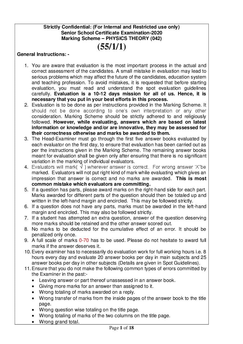
Strictly Confidential: (For Internal and Restricted use only)
Senior School Certificate Examination-2020
Marking Scheme – PHYSICS THEORY (042)
(55/1/1)
General Instructions: -

1. You are aware that evaluation is the most important process in the actual and
correct assessment of the candidates. A small mistake in evaluation may lead to
serious problems which may affect the future of the candidates, education system
and teaching profession. To avoid mistakes, it is requested that before starting
evaluation, you must read and understand the spot evaluation guidelines
carefully. Evaluation is a 10-12 days mission for all of us. Hence, it is
necessary that you put in your best efforts in this process.
2. Evaluation is to be done as per instructions provided in the Marking Scheme. It
should not be done according to one’s own interpretation or any other
consideration. Marking Scheme should be strictly adhered to and religiously
followed. However, while evaluating, answers which are based on latest
information or knowledge and/or are innovative, they may be assessed for
their correctness otherwise and marks be awarded to them.
3. The Head-Examiner must go through the first five answer books evaluated by
each evaluator on the first day, to ensure that evaluation has been carried out as
per the instructions given in the Marking Scheme. The remaining answer books
meant for evaluation shall be given only after ensuring that there is no significant
variation in the marking of individual evaluators.
4. Evaluators will mark( √ ) wherever answer is correct. For wrong answer ‘X”be
marked. Evaluators will not put right kind of mark while evaluating which gives an
impression that answer is correct and no marks are awarded. This is most
common mistake which evaluators are committing.
5. If a question has parts, please award marks on the right-hand side for each part.
Marks awarded for different parts of the question should then be totaled up and
written in the left-hand margin and encircled. This may be followed strictly.
6. If a question does not have any parts, marks must be awarded in the left-hand
margin and encircled. This may also be followed strictly.
7. If a student has attempted an extra question, answer of the question deserving
more marks should be retained and the other answer scored out.
8. No marks to be deducted for the cumulative effect of an error. It should be
penalized only once.
9. A full scale of marks 0-70 has to be used. Please do not hesitate to award full
marks if the answer deserves it.
10. Every examiner has to necessarily do evaluation work for full working hours i.e. 8
hours every day and evaluate 20 answer books per day in main subjects and 25
answer books per day in other subjects (Details are given in Spot Guidelines).
11. Ensure that you do not make the following common types of errors committed by
the Examiner in the past:-
• Leaving answer or part thereof unassessed in an answer book.
• Giving more marks for an answer than assigned to it.
• Wrong totaling of marks awarded on a reply.
• Wrong transfer of marks from the inside pages of the answer book to the title
page.
• Wrong question wise totaling on the title page.
• Wrong totaling of marks of the two columns on the title page.
• Wrong grand total.
Page 1 of 18

Page 2

• Marks in words and figures not tallying.
• Wrong transfer of marks from the answer book to online award list.
• Answers marked as correct, but marks not awarded. (Ensure that the right tick
mark is correctly and clearly indicated. It should merely be a line. Same is with
the X for incorrect answer.)
• Half or a part of answer marked correct and the rest as wrong, but no marks
awarded.

12. While evaluating the answer books if the answer is found to be totally incorrect, it
should be marked as cross (X) and awarded zero (0)Marks.

13. Any unassessed portion, non-carrying over of marks to the title page, or totaling
error detected by the candidate shall damage the prestige of all the personnel
engaged in the evaluation work as also of the Board. Hence, in order to uphold
the prestige of all concerned, it is again reiterated that the instructions be followed
meticulously and judiciously.

14. The Examiners should acquaint themselves with the guidelines given in the
Guidelines for spot Evaluation before starting the actual evaluation.

15. Every Examiner shall also ensure that all the answers are evaluated, marks
carried over to the title page, correctly totaled and written in figures and words.

16. The Board permits candidates to obtain photocopy of the Answer Book on request
in an RTI application and also separately as a part of the re-evaluation process
on payment of the processing charges.

Page 2 of 18

Page 3

MARKING SCHEME: PHYSICS
QUESTION PAPER CODE: 55/1/1
Q.No. Value Points/Expected Answer Marks Total
Marks
SECTION A
1 (A) 1 1

no net charge is enclosed by the surface
2 (C) 1 1

−𝑞𝐿𝐸
3 (C) 1 1

No current flows in the potentiometer wire at balance
4 (B) 1 1

3:2
5 (D) 1 1

material of the turns of the coil
6 (A) 1 1

increases the resolving power of telescope
7 (A) 1 1

1.47
8 (A) 1 1

red colour
9 (D) 1 1

The stability of atom was established by the model
10 (C) 1 1

1:3
11 0.15G 1 1
12 Eddy 1 1
13 Four times 1 1
14 Integral 1 1
OR
Nucleons
15 √3 1 1
16 1 1
∮ 𝐵. 𝑑𝑙 = 𝜇0 (𝑖𝑐 + 𝑖𝑑 )
17 Decreases or reduce 1 1
18 4.8 fermi 1 1
OR
1
1836
19 M2 1 1
20 Si & Ge cannot be used for fabrication of visible LED because 1 1
their energy gap is less 1.8eV

Page 3 of 18

Page 4

SECTION B
21
(a) Principle 1 mark
(b) Circuit diagram for determining unknown resistance
of meter bridge 1 mark

½

Meter bridge works on the principle of a balanced wheatstone
bridge.
𝑅1 𝑅 ½
= 𝑅3 at null point when Ig=0
𝑅
2 4
(unknown)

1 2

22
Formula for parallel plate ½ mark
Calculation of effective capacitance of the combination
1 mark
Relation K, K1 and K2 ½ mark

𝑘𝜖𝑂 𝐴
𝐶1 = ½
𝑑
Capacitor are connected in series
𝐶 ′ 𝐶 ′′ 2𝐾1 𝐾2 ∈𝑂 𝐴
𝐶2 = ′ = ( ) 1
𝐶 + 𝐶 ′′ 𝐾1 + 𝐾2 𝑑

C1=C2

2𝐾1 𝐾2 ½
𝐾=
𝐾1 + 𝐾2 2

Page 4 of 18

Page 5

23
Definition of half life 1 mark
Determination of ratio R1 and R2 1 mark

The time interval in which the number of radioactive nuclei
reduced / disintegrated to half of initial value
1
Let R1 and R2 be their activities then

𝑅1 = 𝜆1 𝑁1

𝑅2 = 𝜆2 𝑁2 ½
𝑁1
𝑅1 𝜆1 𝑁1 𝑇 𝑁1 𝑇2
= = 1 =
𝑅2 𝜆2 𝑁2 𝑁2 𝑁2 𝑇1 ½ 2
𝑇2
24
Definition of wavefront ½ mark
Figure ½ mark
Derivation of law of refraction 1 mark

Wavefront is defined as the surface of constant phase;
Alternatively
It is a locus of all the points in the same phase of disturbance ½

½

𝐵𝐶 𝜐1 𝑡
sin 𝑖 = = ½
𝐴𝐶 𝐴𝐶
𝐴𝐸 𝜐2 𝑡
sin 𝑟 = =
𝐴𝐶 𝐴𝐶
sin 𝑖 𝜐1
= ½ 2
sin 𝑟 𝜐2

OR

Page 5 of 18

Page 6

Lens Maker’s formula 1 mark
Derivation of focal length of three lenses 1 mark

1 1 1 1
∵ − = (𝑛 − 1) ( − ) − − − − − −1 1
𝜐 𝑢 𝑅1 𝑅2

When u=∞ and 𝜐 = 𝑓
1 1 1 ½
= (𝑛 − 1) ( − ) − − − − − − − − − 2
𝑓 𝑅1 𝑅2

𝑛2
[𝑛 = ]
𝑛1
From Eq 1 and 2
1 1 1 ½ 2
= − 𝑡ℎ𝑒𝑛 𝑙𝑒𝑛𝑠 𝑓𝑜𝑟𝑚𝑢𝑙𝑎
𝑓 𝜐 𝑢
1 1 1
[Even if the student derives = − for biconvex lens, award
𝑓 𝜐 𝑢
1 ½ marks]
25
Magnetic field at point P 1 ½ mark
Curve ½ mark

a)
𝜇𝑜 𝐼
𝐵= ½
2𝜋𝑥

𝜇𝑜 𝐼 𝜇0 𝐼 𝜇𝑜 𝐼(𝑑 − 2𝑥)
𝐵𝑃 = 𝐵1 − 𝐵2 = − = 1
2𝜋𝑥 2𝜋(𝑑 − 𝑥) 2𝜋(𝑑 − 𝑥)𝑥

b)

½ 2

Page 6 of 18

Page 7

26
Electrostatic force= centripetal force ½ mark
𝑛ℎ
Angular momentum= ½ mark
2𝜋

Formula for radius of nth orbit 1 mark

𝐹𝑐 = 𝐹𝐸

𝑚𝑒 𝜐𝑛2 𝐾𝑧𝑒 2 ½
= 2
𝑟𝑛 𝑟𝑛

𝑚𝑒 𝑣𝑛2 𝑟𝑛 = 𝐾𝑧𝑒 2
By Bohr’s second postulate

𝑛ℎ
𝐿 = 𝑚𝑒 𝜐𝑛 𝑟𝑛 = ½
2𝜋

𝑛2 ℎ2
𝑟𝑛 =
4𝜋 2 𝑚𝑒 𝑘𝑒 2 𝑍
2 2
𝑛 ℎ
𝑟𝑛 = 2 (∵ 𝑍 = 1) 1 2
4𝜋 𝑚𝑒 𝑘𝑒 2

OR

Two observations 1 mark
Diagram 1 mark

a) ½
(i) There exists a threshold frequency below which no
photoelectron is ejected.
(ii) KE of electron depends linearly on frequency and is ½
independent of intensity of radiation.
[or any other correct observation]
b)

1 2

[only curve is essential to draw]

Page 7 of 18

Page 8

27
Explanation of depletion layer and potential barrier
½ + ½ mark
Effect on depletion layer ½ mark
Effect on Potential barrier ½ mark

The small region in the vicinity of the junction which is depleted of ½
free charge carrier and has only immobile ions is called depletion
region/ layer.

The accumulation of negative charges in p - region and positive ½
charges in n- region set up a potential difference across the junction,
which acts as a barrier and is called barrier potential.
½
In forward bias (a) width of depletion layer decreases
(b) value of potential decreases ½ 2
SECTION C
28
a) Internal resistance 1 ½ mark
b) Voltage across R 1 ½ mark

(a)

Current drawn from cell -1
𝐸1 − 𝑉
𝐼1 = ½
𝑟1
Current drawn from cell -2
𝐸2 − 𝑉
𝐼2 =
𝑟2
Resultant current 𝐼 = 𝐼1 + 𝐼2

On solving
𝐸1 𝑟2 + 𝐸2 𝑟1 𝑟2 + 𝑟1
∴𝐼= −𝑉( )
𝑟1 𝑟2 𝑟1 𝑟2

𝐸1 𝑟2 + 𝐸2 𝑟1 𝑟1 𝑟2
∴𝑉= −𝐼( )
𝑟1 𝑟2 𝑟2 + 𝑟1

𝑉 = 𝐸𝑒𝑞 − 𝐼𝑟𝑒𝑞

𝐸1 𝑟2 + 𝐸2 𝑟1 ½
𝐸𝑒𝑞 =
𝑟1 + 𝑟2

𝑟1 𝑟2 ½
𝑟𝑒𝑞 =
𝑟2 + 𝑟1
Page 8 of 18

Page 9

𝑟1 𝑟2 2×2 ½
𝑟𝑒𝑓𝑓 = = = 1Ω
𝑟1 + 𝑟2 2 + 2
Current through R
𝐸𝑒𝑓𝑓𝑒𝑐𝑡 5 5
𝐼= = = 𝐴 ½
𝑅 + 𝑟𝑒𝑓𝑓 10 + 1 11

P.D across R
5
= × 10 = 4.54 𝑣𝑜𝑙𝑡 ½ 3
11
29
a) Writing expression for magnetic moment ½ mark
b) Figure ½ mark
Magnetic field and calculation 2 mark

(a) magnetic moment = M= NIA ½
𝑀 = 𝑁𝐼𝜋𝑟 2

½

According to Biot-sevart law
⃗⃗⃗ × 𝑟|
𝜇0 𝐼 |𝑑𝑙
⃗⃗⃗⃗⃗
𝑑𝐵 = ½
4𝜋 𝑟 3

𝜇0 𝐼 𝑑𝑙
𝑑𝐵 =
4𝜋 𝑟 2
𝑑𝐵⊥components due to diametrically opposite components cancel
out. Only 𝑑𝐵𝑥 components refrain

𝜇0 𝐼𝑑𝑙 ½
𝑑𝐵𝑥 = . 𝑐𝑜𝑠𝜃
4𝜋𝑟 2

𝐵 = ∫ 𝑑𝐵𝑥

𝜇0 𝐼𝑅 2 1 3
𝐵= (𝑎𝑙𝑜𝑛𝑔 𝑥 𝑎𝑥𝑖𝑠)
2(𝑅 2 + 𝑥 2 )3⁄2

Page 9 of 18

Page 10

OR

a) Definition and expression 1 mark
b) Conversion of Galvanometer
(i) into ammeter 1 mark
(ii) Effective resistance 1 mark

a) Deflection per unit current ½
𝜃 𝐵𝑁𝐴
𝐼𝑠 = = ½
𝐼 𝐾
b) (i) By connecting a low resistance (Rs) in parallel to ½
galvanometer such that

(𝐼0 − 𝐼𝑔 )𝑅𝑠 = 𝐼𝑔 𝐺 ½
(ii) effective resistance
1 1 1 𝐺 + 𝑅𝑠
= + =
𝑅𝐴 𝑅𝑠 𝐺 𝑅𝑠 𝐺

𝑠 𝑅 𝐺 1 3
∴ 𝑅𝐴 = 𝐺+𝑅
𝑠

30
(a) Peak value of current and phasor 1 mark
Potential across R ½ mark
Potential across C ½ mark
(b) Phase difference ½ mark
Identification ½ mark

(a)

½

Page 10 of 18

Page 11

Peak value of current
𝑉0 𝑉0 ½
𝐼0 = =
𝑍 √𝑋𝑐2 + 𝑅 2
1
𝑋𝑐 =
𝜔𝐶
𝑉0 𝑅
(𝑖) 𝑉𝑅 = 𝐼0 𝑅 = ½
√𝑋𝑐2 + 𝑅 2

𝑉0 ½
(𝑖𝑖) 𝑉𝑐 = 𝐼0 𝑋𝑐 = ( ) 𝑋𝑐
√𝑋𝐶2 + 𝑅 3
(b) From phasor
𝑋𝑐 ½
𝑡𝑎𝑛𝜙 =
𝑅
Current leads the applied voltage by phase 𝜙 ½ 3
31
a) Dependence on distance D from slit 1 mark
b) Dependence on slit separation d 1 mark
c) Dependence on distance between source and slit
1 mark

(a) Fringe width increases, 𝛽 ∝ 𝐷
1 ½+½
(b) Fringe width decreases, 𝛽 ∝ 𝑑
𝑠 𝜆 ½+½
(c) Fringes disappear because 𝑆 < 𝑑 not satisfied ½+½ 3

32
(a) Speed of light in material medium 1 mark
(b) (i) Identification and Range ½ + ½ mark
(ii) Identification and Range ½ + ½ mark

(a) Speed of light in medium
1 1
𝜐= = 1
√𝜇𝜖 √𝜇0 𝜇𝑟 𝜖0 𝜖𝑟
(b) (i) Microwave range 0.1mt – 1mm ½ +½
(10 m – 10 m)
-3 -1

½+½
(ii) Infrared waves range 1 𝑚𝑚 − 700𝑛𝑚 3
33
KE of α particle 1 mark
Calculation 2 marks

KE of α particle 𝐸𝑘𝛼 = (𝑚𝑦 − 𝑚𝑥 − 𝑚𝛼 )𝑐 2 ½

= 𝑚𝑦 𝑐 2 − 𝑚 𝑥 𝑐 2 − 𝑚𝛼 𝑐 2 ½
= (235 × 7.8 – 231 × 7.835 – 4 × 7.07) MeV ½
= 1833 – 1809.885 – 28.28 ½
= 1833 – 1838.165 = -5.165 MeV 1 3
Page 11 of 18

Page 12

Ek < 0 wrong information
[Award full marks till this step]
34
(a) Circuit diagram 1 mark
Working of Zener diode as DC voltage regulator
1 mark
V-I graph ½ mark
(b) Reason of heavy doping ½ mark

(a)

1

If the input voltage increases, the current through Rs and Zener
diode also increases. This increases the voltage drop across Rs 1
without any changes in the voltage across the Zener diode. This is
because in the breakdown region, Zener voltage remains constant
even though the current through that Zener diode changes.

½

½ 3
(b) To decrease the width of depletion region which increases
electric field at the junction.
SECTION D
35
(a) (i) Electric Field inside hollow sphere 1½ mark
(ii) Electric Field outside hollow sphere 1½ mark
(b) (i) The net outward flux through cylinder 1 mark

(ii) The net charge present inside the cylinder 1 mark

Page 12 of 18

Page 13

(a)
(i)

½

According to Gauss’s Law

𝑞𝑖𝑛 ½
∮ 𝐸⃗ . ⃗⃗⃗⃗⃗
𝑑𝐴 =
∈0

∵ 𝑖𝑛𝑠𝑖𝑑𝑒 ℎ𝑜𝑙𝑙𝑜𝑤 𝑠𝑝ℎ𝑒𝑟𝑒
qin = 0
⃗⃗⃗⃗⃗ = 0
∴ ∮ 𝐸⃗ . 𝑑𝐴
E=0 ½
(ii)

½

𝑞 = 𝜎4𝜋𝑅 2
𝑞 ½
∮ 𝐸⃗ ⃗⃗⃗⃗⃗⃗⃗
. 𝑑𝐴 =
∈0
𝑞
𝐸 ∮ 𝑑𝐴 =
∈0
2
𝜎4𝜋𝑅
𝐸. 4𝜋𝑥 2 =
𝜖0
2
𝜎𝑅 ½
𝐸=
𝜖0 𝑥
b)

(i) The net outward flux through cylinder
𝜙 = 𝐸𝐴 + 𝐸𝐴 = 2𝐸𝐴 𝐴 = 𝜋𝑟 2 ½
= 2 ×200 × 3.14 × 0.05 × 0.05
𝑁
= 3.14 𝑚2
𝐶 ½

(ii) The net charge present inside the cylinder
𝑞 = 𝜖0 𝜙 ½
q= 8.854 × 3.14 × 10-12
= 2.78×10⁻¹¹ C ½ 5

Page 13 of 18

Page 14

OR

a) Expression for potential energy 3 marks
b) Equipotential surface due to isolated -ve charge
1 mark
c) Work done in assembling the charge 1 mark

(a) Work done in bringing q from infinity against the field
E= 𝑞1 𝑉|𝑟⃗⃗⃗1 | 1

Work done on q2 against the field E= 𝑞2 𝑉|𝑟⃗⃗⃗2 |
Work done on q2 against the field due to q1
𝑞1 𝑞2
= 1
4𝜋𝜖0 (𝑟12 )

Potential energy of the system= Total work done in assembling the
system ½
𝑞1 𝑞2
= 𝑞1 𝑉(𝑟⃗⃗⃗1 ) + 𝑞2 𝑉(𝑟⃗⃗⃗2 ) + ½
4𝜋𝜖0 𝑟12

b)

1

c) Work done= charge in potential energy

𝑘𝑞1 𝑞2 𝑘𝑞1 𝑞3 𝑘𝑞2 𝑞31
= + + ½
𝑟12 𝑟13 𝑟23

9 × 109 × 10−12
= [1 × −1 + −1 × 2 + 1 × 2]
0.1
= 9 × 10⁻² [−1 − 2 + 2]
= −9 × 10⁻² 𝐽 ½ 5

Page 14 of 18

Page 15

36
a) Labelled diagram 1 mark
Derivation for torque 1 mark
Justification of radial magnetic field 1 marks
(b) Calculation of radius of the path 2 marks

1

Magnetic forces of AB and CD are equal and opposite and have
different line of action so constitute torque
Force acting on current carrying arms AB and CD
𝐹1 = 𝐹2 = 𝐵𝐼𝑙 = 𝐹 (𝑠𝑎𝑦)
∴ 𝜏 = 𝐹 × 𝑝𝑒𝑟𝑝𝑒𝑛𝑑𝑖𝑐𝑙𝑎𝑟 𝑑𝑖𝑠𝑡𝑎𝑛𝑐𝑒 𝑏𝑒𝑡𝑤𝑒𝑒𝑛 𝑡𝑤𝑜 𝑓𝑜𝑟𝑐𝑒 𝑎𝑟𝑚 ½
∴ 𝜏 = 𝐵𝐼𝑙𝑏𝑠𝑖𝑛𝜃
𝑙𝑏 = 𝐴
𝜏 = 𝐵𝐼𝐴 𝑠𝑖𝑛𝜃
For N turn
𝜏 = 𝐵𝐼𝑁𝐴 𝑠𝑖𝑛𝜃 ½
Radial fields always produce maximum torque and removes the
dependence of torque on 𝜃 1
𝑚𝜐 √2𝑚𝐸𝑘
(b) Radius of circular path = = 1
𝐵𝑞 𝐵𝑞

1 2𝑚𝑞𝑉
= √ 2
𝐵 𝑞

1 2𝑚𝑉 1
= √ =
𝐵 𝑞 2 × 10⁻³
r = 10m 1 5

OR

(a) Labelled diagram 1 mark
Working 1 mark
(i) & (ii) Reason/justification ½ + ½ mark
(b) (i) External force required 1 mark
(ii) Power required 1 mark

Page 15 of 18

Page 16

1

[Note: Diagram with different windings can also be drawn]
When an alternating voltage is applied to the primary, the resulting
current produces an alternating magnetic flux which links the
secondary and induces an emf

Induced emf across primary coil

𝑑∅ ½
𝑒𝑃 = −𝑁𝑝
𝑑𝑡

Induced emf across secondary coil

𝑑∅
𝑒𝑠 = −𝑁𝑠
𝑑𝑡
𝑒𝑠 𝑁𝑠
= =𝑟 ½
𝑒𝑝 𝑁𝑝

(i) to minimise the eddy currents ½
(ii) To reduce the heat loss ½

(b)
(i)
F=BIl
𝐸 𝐵𝜐𝑙
𝐼= =
𝑅 𝑅
𝐵 2 𝜐𝑙 2 ½
𝐹=
𝑅
0.4 × 0.4 × 0.1 × 0.2 × 0.2
=
0.1
= 6.4 × 10⁻³ N ½

𝑃 = 𝐹. 𝜐 = 6.4 × 10−3 × 0.1 ½
= .64 × 10−3 𝑊 ½ 5

Page 16 of 18

Page 17

37
a) Labelled diagram 2 marks
Figure
Expression for resolving power 1 mark
b) Calculation of angular magnification 1 mark
Diameter of image formed by objective lens
1 mark

a)

2

𝐷
Resolving power of telescope = 1.22𝜆 1

𝛽 𝑓 20𝑚 1
b) (i) Angular magnification 𝑚 = 𝛼 = 𝑓𝑜 = 10−2𝑚= 2000
𝑒
(ii)
𝐷 𝑥
= ½
𝑑 𝑓𝑜
𝐷𝑓0 3.5 × 106 × 20
𝑑= = = .18m
𝑥 3.8 × 10⁸ ½ 5

OR

(a) Labelled diagram 1 mark
Derivation of mirror relation 2 marks
(b) Position of image 1 ½ marks
Nature of image 1 ½ marks

1

∆𝐴𝐵𝑃 ~𝐴′ 𝐵 ′ 𝑃
′ ′
𝐴𝐵 𝑃𝐵 ′ ½
= −−−−−−−−−1
𝐴𝐵 𝑃𝐵

Also ∆𝐴′ 𝐵 ′ 𝐹 ~𝑀𝑁𝑃 (for small curvature)

Page 17 of 18

Page 18

𝐴′ 𝐵 ′ 𝐵 ′ 𝐹
∴ =
𝑀𝑃 𝑃𝐹

𝐴′ 𝐵 ′ 𝐵 ′ 𝐹
= −−−−−−−−−−−2
𝐴𝐵 𝑃𝐹

From 1 and 2
𝑃𝐵 ′ 𝐵 ′ 𝐹 ½
= −−−−−−−−−−−3
𝑃𝐵 𝑃𝐹

𝑃𝐵 ′ 𝐵 ′ 𝑃 + 𝑃𝐹 ½
= − − − − − − − −4
𝑃𝐵 𝑃𝐹
𝑃𝐵 = −𝑢 𝑃𝐵 ′ = 𝜈 𝑃𝐹 = −𝑓

𝜈 𝜈−𝑓
=
−𝑢 −𝑓
−𝜈𝑓 = −𝜈𝑢 + 𝑢𝑓
1 1 1 ½
= +
𝑓 𝑣 𝑢
(b) According to lens maker’s formula

1 1 1
= (𝜇 − 1) ( − ) ½
𝑓 𝑅1 𝑅2
for plano convex lens R1→ R and R2→∞

1 (𝜇 − 1) 1.5 − 1
= = ½
𝑓 𝑅 20

∴f=40 cm
1 1 1
= −
𝑓 𝜐 𝑢
1 1 1
= −
40 𝜐 −30

𝜐 = −12 𝑐𝑚 ½
Nature: virtual ½ 5

Page 18 of 18

Document Details

Board / OrgCBSE
ExamClass 12
TypeSolution
Pages18
Updated22 Jul 2026