CBSE Class 12 Marking Scheme 2021 for Physics
Finished viewing? Save it for later —
Download CBSE Class 12 Marking Scheme 2021 for Physics (PDF · 7 pages)About CBSE Class 12 Marking Scheme 2021 for Physics
CBSE Class 12 Marking Scheme 2021 for Physics is available here for free download. Published by CBSE for Class 12, this sample paper can be viewed online or downloaded as a PDF (7 pages). Candidates preparing for Class 12 can use CBSE Class 12 Marking Scheme 2021 for Physics to understand the exam pattern, the type of questions asked, and the overall difficulty level.
Frequently Asked Questions
How can I download CBSE Class 12 Marking Scheme 2021 for Physics?
Open this page and click the Download button to save CBSE Class 12 Marking Scheme 2021 for Physics as a PDF. It is completely free on AglaSem Docs.
Is CBSE Class 12 Marking Scheme 2021 for Physics free to download?
Yes. CBSE Class 12 Marking Scheme 2021 for Physics can be viewed online and downloaded as a PDF free of cost on AglaSem Docs.
How many pages does CBSE Class 12 Marking Scheme 2021 for Physics have?
CBSE Class 12 Marking Scheme 2021 for Physics contains 7 pages, which you can read online or download together as a single PDF.
Where can I find more Class 12 study material?
You can find more Class 12 question papers, sample papers, syllabus, and answer keys on AglaSem Docs.
CBSE Class 12 Marking Scheme 2021 for Physics – Text
Read the full text of this sample paper below — useful to quickly search, copy and reference the content online without downloading the PDF.
📄 View text version (7 pages)
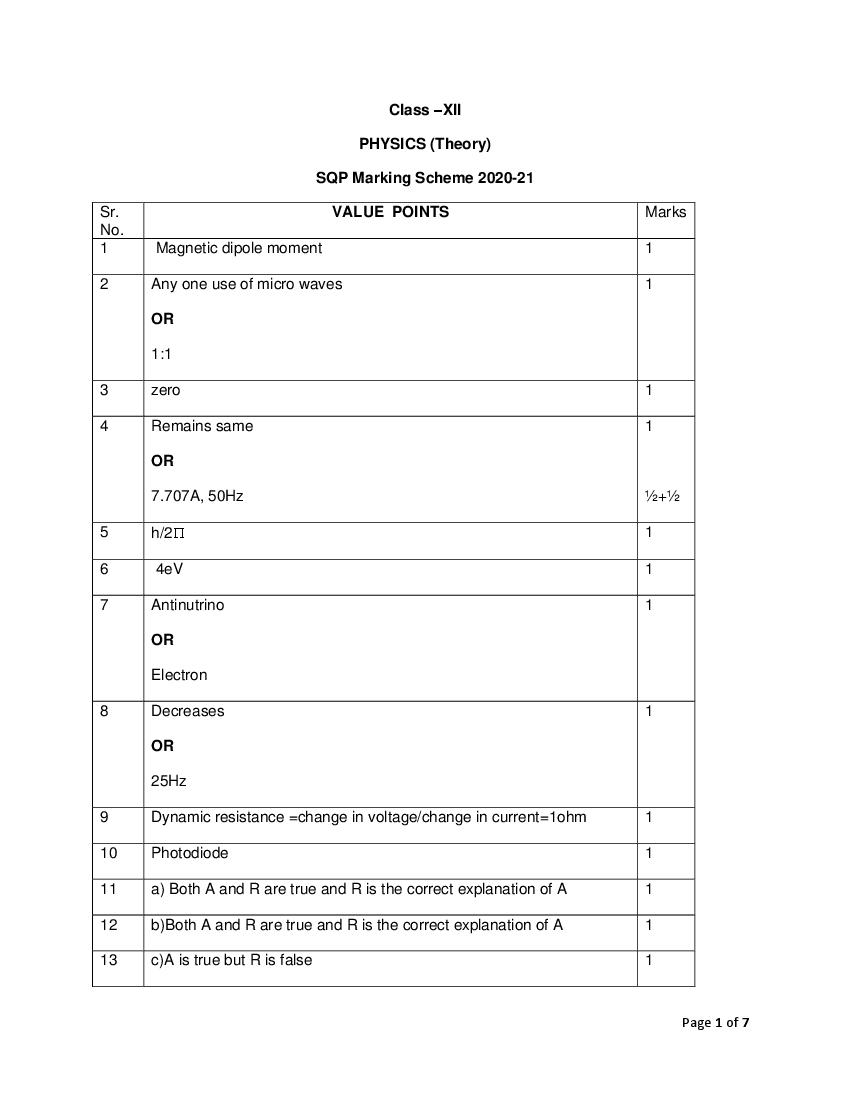
Page 1
PHYSICS (Theory)
SQP Marking Scheme 2020-21
Sr. VALUE POINTS Marks
No.
1 Magnetic dipole moment 1
2 Any one use of micro waves 1
OR
1:1
3 zero 1
4 Remains same 1
OR
7.707A, 50Hz ½+½
5 h/2 1
6 4eV 1
7 Antinutrino 1
OR
Electron
8 Decreases 1
OR
25Hz
9 Dynamic resistance =change in voltage/change in current=1ohm 1
10 Photodiode 1
11 a) Both A and R are true and R is the correct explanation of A 1
12 b)Both A and R are true and R is the correct explanation of A 1
13 c)A is true but R is false 1
Page 1 of 7
Page 2
15 1.c) Copper 4x1 =
4
2.a) car
3.c) zero
4.a) -q
5 b)1.9105 Nm2/C leaving the surface
(any 4 parts to be attempted)
16 1. b) Its critical angle with reference to air is too small 4x1=4
2. a) 2.42
3. c) high refractive index
4. d) increase
5. d) less than first
(any 4 parts to be attempted)
17 Explanation by showing magnetic field directions in all three regions 1
Concluding left of region 1 1
18 Plot of Intensity distribution of diffraction with proper labeling 2
OR
n/d=2/a
n=2d/a ,where d is separation between slit and a width of slit
19 Derivation including both terms electrostatic energy in system and in 1+1
external field
OR
Derivation of relation E=-dV/dr 1+1
Diagram of equipotential surfaces
Page 2 of 7
Page 3
Action of LED 1
For emission in visible range least band energy required is1.8eV ½
21 Calculation of magnetic flux =BA cos ,where =300 =√3/2^10-11Wb 1
Calculation of induced emf E=A cosdB/dt=0.5V 1
22 Path difference=3/2 1
Putting value we will get=3cm 1
23 Well labeled energy band diagram of n-type semiconductor 1
n-type semiconductor ½
electrons-majority charge carriers ½
24 Definition of each term ½+½
Diagram showing relation 1
OR
Bv/BH=tan 1
Putting values,=300 1
25 Two characteristics- virtual and enlarged image and same side of 1
object.
As u and v both negative, we get 1/v=1/u-1/f 1
Interpret y=mx+c ,plot of the graph
Page 3 of 7
Page 4
for
each
plot
Induced current and power, sketch is same as shown above. 1
In case of circular coil, rate of change of area of the loop during its
passage out of field is not constant, hence induced current varies
accordingly.
½
t
27 Circuit diagram 1
1
1
Maximum current drawn will be at R=0
OR
1
Circuit diagram
½
Applying correct formula
½
And caluation of p.d=11.5V
Series resistor limits the current drawn from source 1
Page 4 of 7
Page 5
physical entities –mass and radiation must be symmetrical.If radiation
shows shows dual aspect than matter should do so.
De-Broglie equation- 1
=h/P
For photon –
P=h/C
Therefore,h/P=C/=
As =h/√2mk
So,alpha particle will be having shortest de-Broglie wavelength 1
compared to deutrons.
OR
Main implications-
1. kinetic energy of emitted electrons depends upon frequency,but not
on intensisty of radiation 1
2.there exist a frequency of radiation below which no photoemission
takes place, how high intensity of radiation may be. 1
Explanation wave nature of radiation fails to explain photoelectric
effect 1
29 Derivation of frequency of radiation emitted when a hydrogen atom de 2
excites from level n to level (n-1).
= me4 (2n-1) / (4)3 (h/2)3 n2 (n-1)2 1
Comparing for large values of n, with classical freuency = v / 2r
30 One difference between nuclear fission and nuclear fusion 1
Calculating Q=((m) Fe-2(m) Al)C2 =26.90MeV 1
Justification not possible 1
31 (a) Statement of Gauss law 1
Proof of outward flux due to a point charge Q ,in vacuum within 2
gaussian surface, is independent of its size and shape
(b) Net electric field towards left=/ left 1
Net electric field towards right=/ right 1
Page 5 of 7
Page 6
Definitionof ideal dipole +example ½+
½
Derivation of torque 2
Putting values in correct formula and solving,value of charge and 1
potential energy
Q=810-3 C 1
U=-8J
32 (a) Derivation of instantaneous current i=iosin (ωt +/2) 1
Reactance XC=1/C 1
Phasor diagram showing v and i relation in pure C 1
(b) Explanation that adding R it will behave RC series ac circuit 1+1
Calcuation of current and phase angie
OR
(a)Principle of ac generator 1
(b)Well labelled diagram 1
Brief working and emf expression
2
(c) reason
1
33 (a) Definition of wavefront 1
(b) Ray diagram showing shapes of wavefront
1
1
(c) Proof of Snell’s law 2
Page 6 of 7
Page 7
(a) choice of objective 1
(b) ray diagram of reflecting type telescope 2+1
Formula of magnifying power
(c) stating two advantages 2
Page 7 of 7
Document Details
| Board / Org | CBSE |
| Exam | Class 12 |
| Type | Marking Scheme |
| Pages | 7 |
| Updated | 30 Apr 2026 |