CBSE Class 12 Marking Scheme 2022 for Physics Term 2
Finished viewing? Save it for later —
Download CBSE Class 12 Marking Scheme 2022 for Physics Term 2 (PDF · 9 pages)About CBSE Class 12 Marking Scheme 2022 for Physics Term 2
CBSE Class 12 Marking Scheme 2022 for Physics Term 2 is available here for free download. Published by CBSE for Class 12, this marking scheme can be viewed online or downloaded as a PDF (9 pages). Candidates preparing for Class 12 can use CBSE Class 12 Marking Scheme 2022 for Physics Term 2 to understand the exam pattern, the type of questions asked, and the overall difficulty level.
Frequently Asked Questions
How can I download CBSE Class 12 Marking Scheme 2022 for Physics Term 2?
Open this page and click the Download button to save CBSE Class 12 Marking Scheme 2022 for Physics Term 2 as a PDF. It is completely free on AglaSem Docs.
Is CBSE Class 12 Marking Scheme 2022 for Physics Term 2 free to download?
Yes. CBSE Class 12 Marking Scheme 2022 for Physics Term 2 can be viewed online and downloaded as a PDF free of cost on AglaSem Docs.
How many pages does CBSE Class 12 Marking Scheme 2022 for Physics Term 2 have?
CBSE Class 12 Marking Scheme 2022 for Physics Term 2 contains 9 pages, which you can read online or download together as a single PDF.
Where can I find more Class 12 study material?
You can find more Class 12 question papers, sample papers, syllabus, and answer keys on AglaSem Docs.
CBSE Class 12 Marking Scheme 2022 for Physics Term 2 – Text
Read the full text of this marking scheme below — useful to quickly search, copy and reference the content online without downloading the PDF.
📄 View text version (8 pages)
Page 1
CLASS XII
PHYSICS THEORY
TERM II
SESSION 2021 - 22
MM:35 TIME: 2 Hours
ANS 1
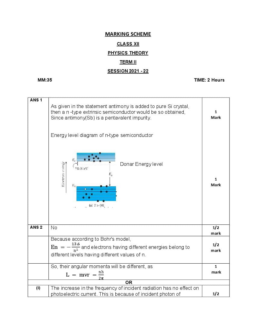
As given in the statement antimony is added to pure Si crystal,
then a n -type extrinsic semiconductor would be so obtained, 1
Since antimony(Sb) is a pentavalent impurity. Mark
Energy level diagram of n-type semiconductor
Donar Energy level
1
Mark
ANS 2 No 1/2
mark
Because according to Bohr's model,
. 1/2
En = − and electrons having different energies belong to
mark
different levels having different values of n.
So, their angular momenta will be different, as 1
mark
L = mvr =
OR
(i) The increase in the frequency of incident radiation has no effect on
photoelectric current. This is because of incident photon of 1/2
Page 2
metal surface.
1/2
mark
(ii) The kinetic energy of the photoelectron becomes more than the
double of its original energy. As the work function of the metal is 1/2
fixed, so incident photon of higher frequency and hence higher mark
energy will impart more energy to the photoelectrons.
1/2
mark
ANS 3 Photodiodes are used to detect optical signals of different 1/2 mark
intensities by changing current flowing through them.
1/2 mark
I-V Characteristics of a photodiode
Page 3
1. In detection of optical signals.
2. In demodulation of optical signals.
3. In light operated switches.
4. In speed reading of computer punched cards. (1/2) X 2= 1
5. In electronic counters mark
(any two out of these or any other relevant application)
SECTION B
ANS 4 From Bohr’s theory, the frequency f of the radiation emitted when
an electron de – excites from level n to level n is given as
2π mk z e 1 1
f= −
h n n
2 marks
Given n = n − 1 , n = n , derivation of it
2π mk z e (2n − 1)
f=
h (n − 1) n
For large n, 2n − 1 = 2n , n − 1 = n and z = 1
1 mark
Thus, f =
which is same as orbital frequency of electron in n orbit.
v 4π mk e
f= =
2πr n h
ANS 5
A junction diode allows current to pass only when it is forward
biased. So, if an alternating voltage is applied across a diode the 1 mark
current flows only in that part of the cycle when the diode is
forward biased. This property is used to rectify alternating voltages
and the circuit used for this purpose is called a rectifier.
1 mark
Circuit Diagram
Page 4
Working with input and output waveforms
ANS 6 Number of atoms present in 2 g of deuterium = 6 × 10
Number of atoms present in 2.0 Kg of deuterium = 6 × 10 1 mark
Energy released in fusion of 2 deuterium atoms
= 3.27 MeV
Energy released in fusion of 2.0 Kg of deuterium atoms
.
= × 6 × 10 MeV
= 9.81 × 10 MeV 1 mark
= 15.696 × 10 J
Energy consumed by bulb per sec = 100 J
. ×
Time for which bulb will glow = s = 4.97 × 10 𝑦𝑒𝑎𝑟
1 mark
ANS 7 A locus of points, which oscillate in phase is called a wavefront.
OR
A wavefront is defined as a surface of constant phase. 1 mark
1 mark
Page 5
Proof n sin i = n sin r (Derivation) 1 mark
This is the Snell’s law of refraction.
ANS 8 Diagram of Compound Microscope for the final image formed at D:
(a)
𝟏
𝟏
𝟐
marks
(b) m = 30, f = 1.25 cm, f = 5 cm
when image is formed at least distance of distinct vision,
D = 25cm
Angular magnification of eyepiece
D 25 1/2 mark
m = 1+ = 1+ =6
f 5
Total Angular magnification, m = m m ⇒ m = = =5
As the objective lens forms the real image,
m = = −5 ⇒ v = −5u
1/2 mark
using lens equation, u = −1.5 cm, v = −5 × (−1.5)cm = +7.5 cm
Given v = −D = −25 cm, f = +5 cm, u = ?
using again lens equation u =
Thus, object is to be placed at 1.5 cm from the objective and
separation between the two lenses should be 1/2 mark
L = v + Iu l = 11.67 cm
OR
ANS 8
(a) Ray diagram of astronomical telescope when image is formed at 𝟏
𝟏 marks
𝟐
infinity.
Page 6
Magnifying power. ½ mark
m = f /f = (140/5) = 28
(ii) When the final image is formed at the least distance of 1 mark
distinct vision (25 cm) :
m= 1+ = (28 x 1.2) = 33.6
ANS 9
λ = 2000 Å = (2000 × 10 )m
W = 4.2eV
h = 6.63 × 10 JS
(a) Using Einstein's photoelectric equation 1 mark
K. E. = (6.2 – 4.2) eV = 2.0 eV
The energy of the emitted electrons does not depend upon 1 mark
(b)
intensity of incident light; hence the energy remains unchanged.
(c) For this surface, electrons will not be emitted as the energy of 1 mark
incident light (6.2 eV) is less than the work function (6.5 eV) of the
surface.
ANS 10 Given a = 1.5
Focal length of the given convex lens when it is placed in air is
f = + 20 cm
Refractive index of the given medium with respect to air is
a = 1.25
New focal length of the given convex lens when placed in a
medium is f
= a −1 + ------(A) 1/2 mark
1/2 mark
= m −1 + ------(B)
Dividing (A) by (B), we get
f a −1 (1.5 − 1) 0.5 5
= = = = = 2.5
f m −1 (1.2 − 1) 0.2 2
. 1 mark
f = 2.5f = (2.5 × 20)cm = +50cm as m = = = 1.2
.
New focal length is positive.
The significance of the positive sign of the focal length is that given 1/2 mark
convex lens is still converging in the given medium.
1/2 mark
ANS 11.
(a) Microwaves are suitable for the radar system used in aircraft
Page 7
Range of frequency of microwaves is 108 Hz to 1011 Hz.
(b)
If the Earth did not have atmosphere, then there would be absence
of greenhouse effect of the atmosphere. Due to this reason, the 1 mark
temperature of the earth would be lower than what it is now.
(c)
An e.m. wave carries momentum with itself and given by
P = Energy of wave(U)/ Speed of the wave(c) 1 mark
= U/c
when it is incident upon a surface it exerts pressure on it.
OR
ANS. 11 The total intensity at a point where the phase difference is ∅, is
(a)
given by 𝐼 = 𝐼 + 𝐼 + 2 𝐼 𝐼 𝐶𝑂𝑆 ∅. Here 𝐼 and 𝐼 are the
intensities of two individual sources which are equal. 2 marks
When ∅ is 0, I = 4𝐼 .
When ∅ is 90o, I = 0
Thus intensity on the screen varies between 4𝐼 and 0.
Intensity distribution as function of phase angle, when diffraction of
ANS. 11
(b)
light takes place through coherently illuminated single slit
1 mark
ANS 12.
(a) Ans (i) Refraction, Total internal reflection 1 mark
(b) Ans iii) sin-1( )
1 mark
a =
⇒ sin C = ⇒ C = sin
Page 8
The refractive index of the core should be greater than the
refractive index of the cladding.
(d)
1 mark
Ans (iv) increases
l = = ,ω = =
μ >μ
(e) Thus C > C
1 mark
Ans (ii) 0 < i < 60° , 1 =
.
Sin C = = 0.8571
.
⇒ C = 59°
Total internal reflection will occur if the angle 𝑖 > 𝑖 ,
i.e., if 𝑖 > 59o or when r < rmax’ where rmax = 90o – 59o = 31o.
Using Snell’s law,
= 1.68
or 𝑆𝑖𝑛 𝑖 = 1.68 × 𝑆𝑖𝑛 𝑟
= 1.68 x sin 31o = 1.68 x 0.5150 = 0.8662
∴ 𝑖 = 60o
Thus all incident rays which make angles in the range 0 < 𝑖 <
60 with the axis of the pipe will suffer total internal
reflections in the pipe.
Document Details
| Board / Org | CBSE |
| Exam | Class 12 |
| Type | Solution |
| Pages | 9 |
| Language | english |
| Updated | 30 Apr 2026 |